Week-7 Challenge: DC Motor Control
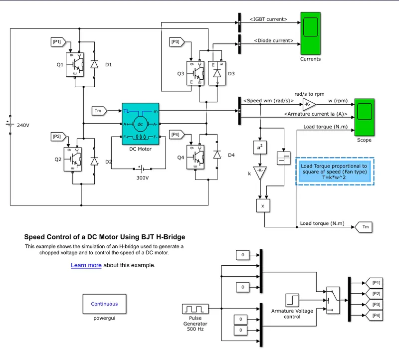
QUE 1 ANS - A) MATLAB demo model named ‘Speed control of a DC motor using BJT H-bridge is shown below
Discription -
The Bipolar Junction Transistor (BJT) when used for power switching applications, operates as an IGBT. When it is conducting (BJT operating in the saturated region), a forward voltage Vf is developed between collector and emitter (in the range of 1 V). Therefore, the IGBT block can be used to model the BJT device.
The IGBT block does not simulate the gate current controlling the BJT or IGBT. The switch is controlled by a Simulink® signal (1/0). The DC motor uses the preset model (5 HP 24V 1750 rpm). It simulates a fan type load (where Load torque is proportional to square of speed). The armature mean voltage can be varied from 0 to 240 V when the duty cycle (specified in the Pulse Generator block) is varied from 0 to 100%.
The H-bridge consists of four BJT/Diode pairs (BJT simulated by IGBT models). Two transistors are switched simultaneously: Q1 and Q4 or Q2 and Q3. When Q1 and Q4 are fired, a positive voltage is applied to the motor and diodes D2-D3 operate as free-wheeling diodes when Q1 and Q4 are switched off. When Q2 and Q3 are fired, a negative voltage is applied to the motor and diodes D1-D4 operate as free-wheeling diodes when Q2 and Q3 are switched off.
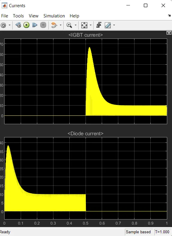
B) - 1. The graph shows the IGBT current and Diode current.
2. Graph shows the Armature current, load torque
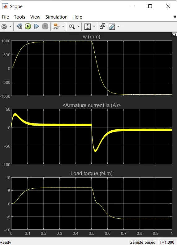
At starting there is sudden spike increases in current at 0 sec also and at 0.5 sec also means at transition from positive to negative direction of rotation we observe a high current, this is due to the transient switching occuring in the circuit.
As there is already current flowing in the circuit and on charging of switches after 0.5 sec, the current in the circuit adds to the changed direction of current and we observe a surge in current.
The surge in the current can be reduced by reducing the duty cycle.
In above result, the duty cycle is selectrd as 75%.
By changing the duty cycle from 75% to 50% the current surge can be reduced tremendously.
C) - The Four-Quadrant Chopper DC Drive (DC7) block is shown below.
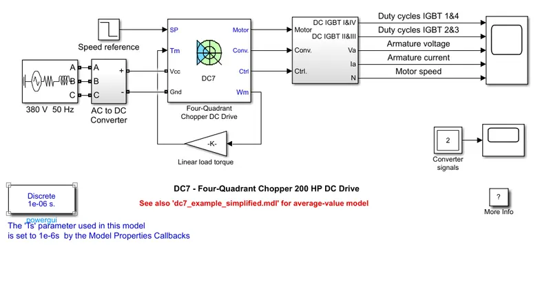
Comparison with H BRIDGE and QUADRANT CHOPPER
1. H bridge work in open loop system and quadrant chopper works in closed loop system.
2. In H bridge motor is not separately excited but in Quadrant chopper motor is separately excited with a constant 150 V DC field voltage source.
3. H bridge cannot work in regenerative mode but Quadrant chopper work in all 4 quadrants.
4. Simulation is contineous in H bridge and discrete in Quadrant chopper.
5. Simulation takes more time and less efficient of H bridge compared to Quadrent chopper.
QUE 2 ANS -
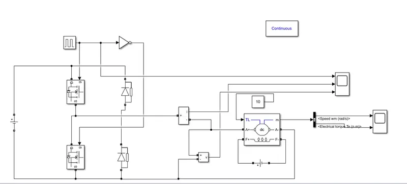
The above model is a 2nd quadrant chopper modeled using simulink software. The main components are :
A pulse genenrator
current measurement
Diode
MOSFET
Scope
NOT gate
Battery
Working - Type C chopper is obtained by connecting type A and type B chopper in parallel.
We will always get a positive output voltage Vo as the freewheeling diode FD is present across the load.
When the chopper is on freewheeling diode starts conducting and the output and the voltage Vo will be equal to Vs.
The direction of the load current io will be reversed. The current io will be flowing towards the source and it will be positive regardless of the choppper is on or the FD conducts.
The load current will be negative if the chopper is ot the diode D2 conducts.
We can say that chopper and FD operates together as a type A chopper in the first Quadrant.
In the second quadrant, the chopper and D2 will operate together as type B chopper.
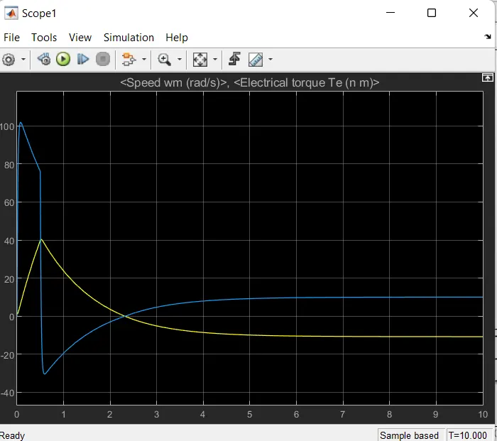
Result - In the result shows at maximum speed, Torque is decreasing and Speed also same at same point but again at point the speed again start increasing torque goes in negative with respect to speed.
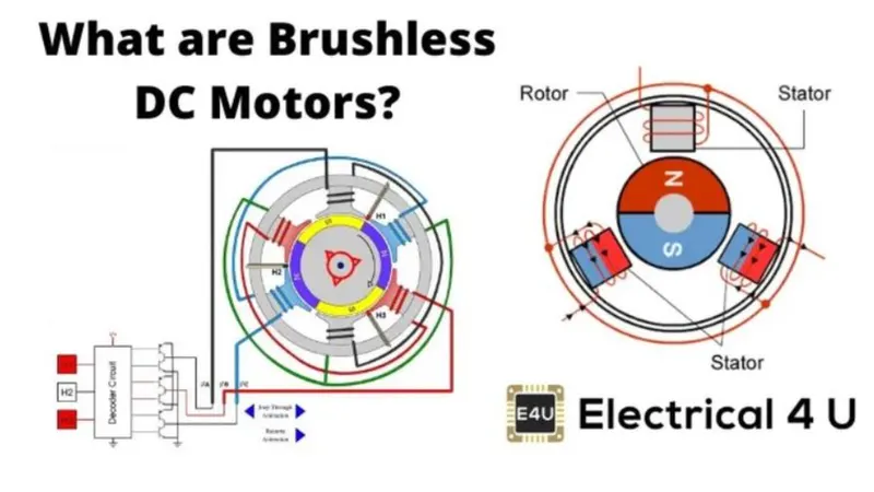
QUE 3 ANS - Working principle and operation of BLDC Motor
1. BLDC motor works on a principle similar to that of a conventional DC motor. i.e. the Faradays law which states that whenever a current carrying conductor placed in a magnetic force it experiences a force.
2. As a consequence of reaction force, the magnet will experience an equal and opposite force. In the case BLDC motor, the current carrying conductor is stationary while the permanent magnet moves.
3. When the stator coils are electrically switched by a supply source, it becomes an electromagnet and starts producing the uniform field in the air gap. Though the source of supply is DC, switching makes to generate an AC voltage waveform with a trapezoidal shape.
4. Due to the force of interaction between the electromagnet stator and permanent magnrt rotor, the rotor continues to rotate.
5. Consider the figure below in which the motor stator is excited based on different switching states. With the switching of winding as high and low signals. Corresponding winding energized as North and South poles.
6. The permanent magnet rotor with North and South poles align with stator poles causing the motor to rotate.
7. Observe that the motor produces torque because of the development of attraction forces. In this way motor moves in a clockwise direction.