Week-7 Challenge: DC Motor Control
1) a. An H-bridge is a simple circuit that allows us to control the direction of a DC motor.
In general, an H-bridge is a very simple circuit having four switching elements in a H like shape, with the load in the centre:
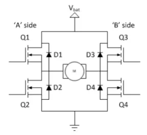
In most high-voltage applications, the switching elements (Q1..Q4) are bipolar or FET transistors; in other cases, IGBTs are used.
There are other integrated solutions, but for the most part, whether the switching elements are integrated with their control circuits is irrelevant for our topic. The diodes (D1..D4) are known as catch diodes and are typically Schottky in design.The bridge's top end is linked to a power source (such as a battery), while the bottom end is grounded.
Although there are some evident limitations, all four switching parts can be turned on and off independently. Though the load can be anything we desire, H-bridges are most commonly used with brushed DC or bipolar stepper motors (steppers require two H-bridges per motor). The next sections will focus on brushed DC motor driver applications.
The model of " Speed control of DC motor using BJT H bridge " is given below
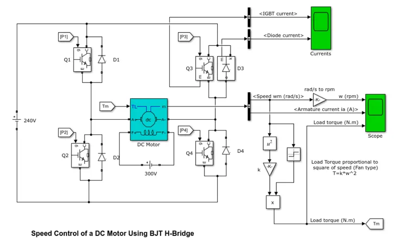
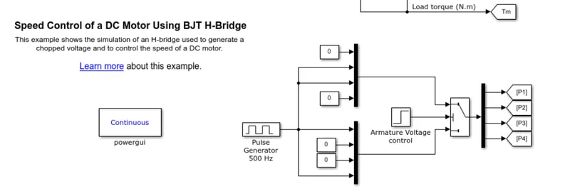
When employed in power switching applications, the Bipolar Junction Transistor (BJT) functions as an IGBT. A forward voltage Vf (in the range of 1 V) is created between collector and emitter when it is conducting (BJT working in the saturated area). As a result, the BJT device can be modelled using the IGBT block. The gate current controlling the BJT or IGBT is not simulated by the IGBT block. A Simulink signal (1/0) is used to control the switch.
Model Description
The preset model uses DC motor (5 HP 24V 1750 rpm). It replicates a fan load (in which the torque is proportional to the square of the speed). When the duty cycle (given in the Pulse Generator block) is changed from 0 to 100%, the armature means voltage can be varied from 0 to 240 V. Four BJT/Diode pairs make up the H-bridge.Q1 and Q4 or Q2 and Q3 are indeed switched at the same time. When Q1 and Q4 are turned on, a positive voltage is given to the motor, and when Q1 and Q4 are turned off, diodes D2-D3 work as free-wheeling diodes.
When Q2 and Q3 are activated, a negative voltage is given to the motor, and when Q2 and Q3 are turned off, diodes D1-D4 operate as free-wheeling diodes.
Simulation
The motor starts in the positive direction with a duty cycle of 75% (mean DC voltage of 180V). At t= 0.5 sec., the armature
voltage is suddenly reversed and the motor runs in the negative direction.
'Scope' shows motor speed, armature current, and load torque and 'Currents' shows currents flowing in BJT Q3 and
diode D3.
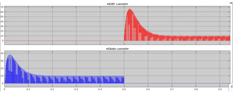
As can be seen from the graph above, current travels via diode D3 from 0 to 0.5 seconds, and through Q3 from 0.5 seconds to 1 second.
With a duty cycle of 75%, the motor starts in the positive direction (mean DC voltage of 180V). The armature voltage is abruptly reversed at t=0.5 sec, and the motor runs in the other direction.
'Scope' displays the motor speed, armature current, and load torque, while 'Currents' displays the currents flowing through the BJT Q3 and diode D3.
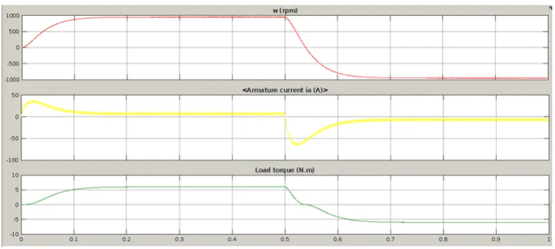
The graphs above illustrate the waveforms for speed, armature current, and load torque. We can see from the armature current graph that there is a rapid surge in current at 0 sec and 0.5 sec. We can observe that as the voltage in the circuit varies, the motor speed changes as well.
We see a large surge in current as the rotation direction changes from positive to negative. This is due to the circuit's transient switching.
Because current is already flowing in the circuit, when the switches are changed after 0.5 seconds, the current in the circuit adds to the changed direction of current, resulting in a surge.
b.
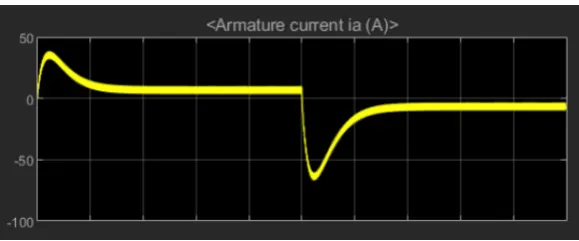
The armature current graph shows that there is a dramatic spike increase in current at 0 sec and at 0.5 sec, indicating that at the transition from positive to negative direction of rotation, there is a large surge in current. This is due to transient switching in the circuit.
Because current is already flowing in the circuit, when the switches are flipped after 0.5 seconds, the current in the circuit adds to the changed direction of current, resulting in a surge in current. The duty cycle can be shortened to reduce the current surge.
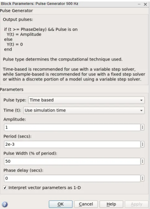
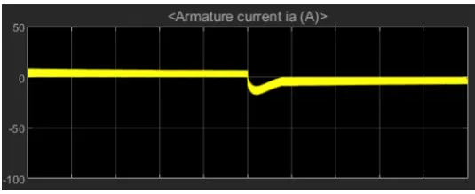
As a result, we can see that lowering the duty cycle from 75% to 50% reduces the armature current surge.
c. A four-quadrant, DC-supplied chopper (or DC-DC PWM converter) drive for DC motors is represented by the Four-Quadrant Chopper DC Drive (DC7) block. With four-quadrant operation, this drive has closed-loop speed control. The machine's reference armature current is output by the speed control loop. The chopper duty cycle corresponding to the commanded armature current is calculated using a PI current controller. The requisite PWM signals for the chopper are then obtained by comparing the duty cycle to a sawtooth carrier signal.
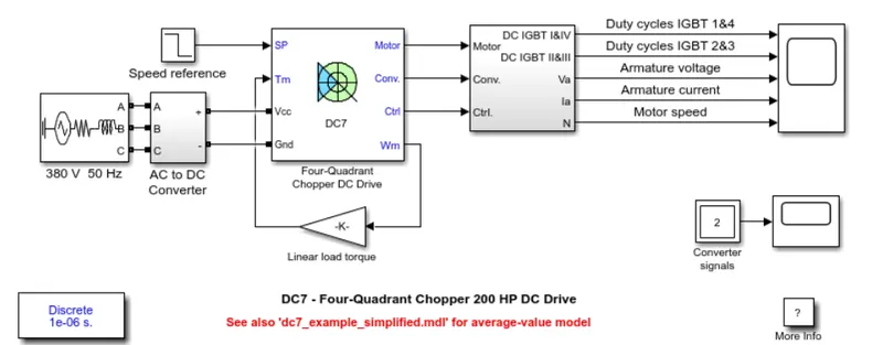
1. The 4 quadrant chopper works in all four modes like Forward motoring, Forward breaking, Reverse motoring
Reverse breaking. But the BJT h bridge model works on only two modes. They are : Forward motoring, Reverse motoring.
2.The current signals are transited from one switch to another to alter the direction of rotation of the motor from forward to reverse and vice versa, whereas in the H bridge model, the direction of rotation is changed by changing the polarity of the current.
3. The H bridge type has a low switching frequency, but the 4 quadrant chopper has a high switching frequency.
4. Because of the high switching frequency, the armature current in the 4 quadrant chopper has a little spike at the transition from one switch to the next, whereas the H bridge model has a large spike.
5. The H bridge type is employed in robotics, whereas the 4 quadrant chopper is used in industrial applications.
--------------------------------------------------------------------------------------------------------------------------
2.
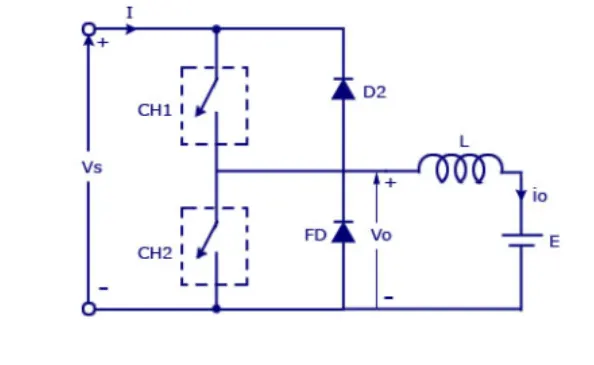
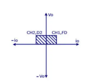
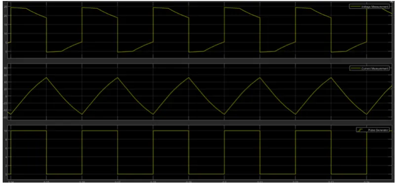
By linking type –A and type –B choppers in parallel, a type C chopper is created. Because the freewheeling diode FD is present across the load, we will always get a positive output voltage V. The freewheeling diode begins to conduct when the chopper is turned on, and the output voltage v equals V. The load current I will be reversed in direction. Regardless of whether the chopper is on or the FD conducts, the current I will flow towards the source and will be positive. If the chopper or diode D2 conducts, the load current will be negative.If the chopper or diode D2 conducts, the load current will be negative. In the first quadrant, the chopper and FD work together as a type-A chopper. The chopper and D2 will work together as type –B choppers in the second quadrant.
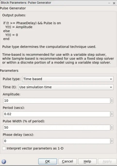
The Simulink Model of a Two Quadrant Chopper is shown below.
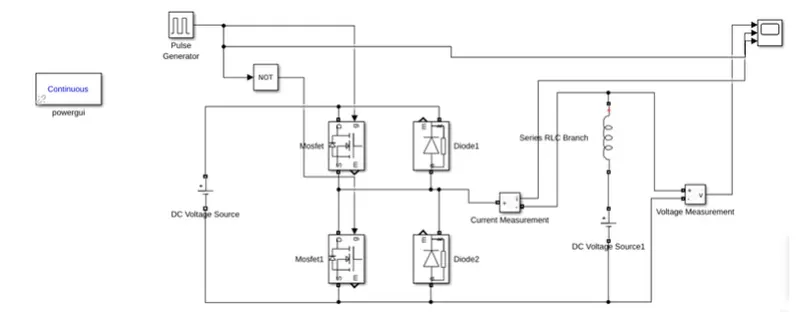
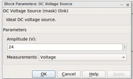
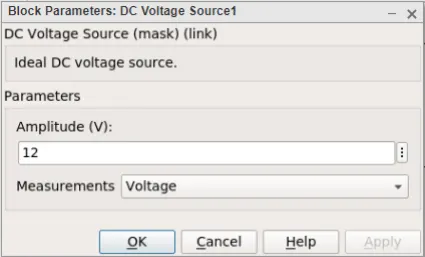
Let's connect two MOSFET blocks and two diode blocks as shown in the circuit diagram. As illustrated, the dc voltage source is attached.Let the dc voltage source's voltage be 24 volts.
Results:
--------------------------------------------------------------------------------------------------------------------------
3.A Brushless DC Motor, BLDC accomplishes commutation electronically using rotor position feedback to determine when to switch the current. The BLDC motor is electrically commutated by power switches instead of brushes. The structure of Brushless DC Motor, BLDC is shown in figure below.
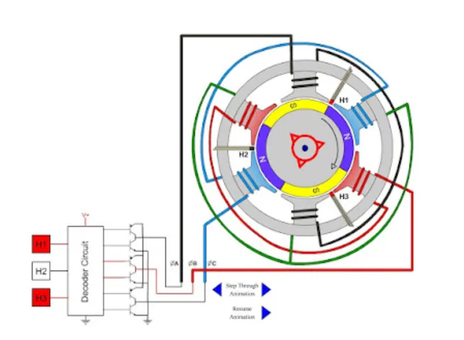
In simple words, a BLDC has no brushes and commutator for having unidirectional torque rather integrated inverter / switching circuit is used to achieve unidirectional torque. That is why these motors are, sometimes, also referred as Electronically Commutated Motors.
Construction of a BLDC Motor:
Like any other electric motor, a BLDC motor also has a stator and a rotor. Here we will consider Stator and Rotor each separately from construction point of view.
BLDC Stator:
There are three types of the BLDC motor:
- Single-phase
- Two-phase
- Three-phase.
Stator for each type has the same number of windings. The single-phase and three-phase motors are the most widely used. The simplified cross section of a single-phase and a three-phase BLDC motor is shown in figure below. The rotor has permanent magnets to form two magnetic pole pairs, and surrounds the stator, which has the windings.
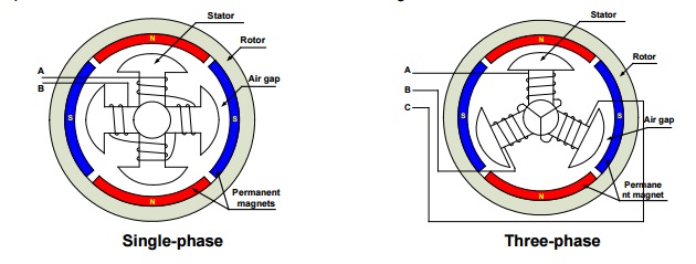
A single-phase motor has one stator winding wound either clockwise or counter-clockwise along each arm of the stator to produce four magnetic poles as shown in above figure.
A three phase BLDC motor has three windings. Each phase turns on sequentially to make the rotor revolve.
Rotor:
A rotor consists of a shaft and a hub with permanent magnets arranged to form between two to eight pole pairs that alternate between north and south poles. Figure below shows cross sections of three kinds of magnets arrangements in a rotor.

How Does A Brushless DC Motor Work?
BLDC Motor operation is based on the attraction or repulsion between magnetic poles. Using the three-phase motor as shown in figure below, the process starts when current flows through one of the three stator windings and generates a magnetic pole that attracts the closest permanent magnet of opposite pole.

The rotor will move if the current shifts to an adjacent winding. Sequentially charging each winding will cause the rotor to follow in a rotating field. The torque in this example depends on the current amplitude and the number of turns on the stator windings, the strength and the size of the permanent magnets, the air gap between the rotor and the windings, and the length of the rotating arm.
The benefits off a BLDC motor include:
- Efficiency- with a BLDC motor, you get more torque per watt ratio. Reasons for the high efficiency include the fewer moving parts, pulsed power control, and reduced power losses since it uses no sliding contacts.
- High Torque to Weight Ratio– when designing a brushless DC motor, its working principle allows engineers miniaturize parts without a significant reduction of torque. These motors are commonly used in small electric products where brushed motors would be too big.
- Low Noise- because they do not use brushes and sliding contacts, BLDC motors do not produce a lot of noise. That explains one of the reasons for their use in computer parts such as fans and hard disks, among other low-noise applications.
- Longer Lifespan- with fewer wear parts, brushless motors last a long time. Most BL motors provide more than 10 000 hours of service life, which is one of the longest lifespan for an electric motor.
- Safe Operation– brushless DC motors do not produce sparks when in operation, which makes them suit environments where sparks could ignite vapor and start a fire. These include hospitals and factories. In brushed motors, the mechanical switching of voltage that happens between the brushes and commutator and leads to arcing.
- Effective Cooling- the brushless DC construction involves placing coil windings on the outer casing of the motor assembly. This helps with cooling through conduction. BL motors also use pulsed power and do not produce a lot of heat.
- Sealed Construction- with the low heat generated by BL motors and heat dissipation through conduction, brushless motors usually do not need to be actively cooled by air. This allows for closed assemblies, shutting off dust and other elements that would cause damage.
- Reduced Electromagnetic Interference– BLDC motors do not cause electromagnetic interference (EMI). The commutation is electronic, which allows for a smooth change of current direction.
- Reduced Centrifugal Force on Rotor- the brushless DC motor rotor is normally a permanent magnet or magnets. That means reduced centrifugal force when the motor is working, and a better dynamic response.
- Reduced Maintenance Costs- brushless motors are easier and less costly to maintain. There are neither brush wear to worry about no commutator erosion to take care of. Only the bearing is bound to wear out, which is usually after many hours of service.
A BLDC motor also has its downsides, which makes it unsuitable for specific uses. The disadvantages include:
- High Initial Cost- the brushless DC motor price is one of the highest, and can go up to several hundred dollars for the large types of the motor. Reasons for the high cost include the electronic controllers used with them and the inclusion of sensors in the assembly.
- Delicate Electronics and Sensors- BL motors rely on electronic controllers and (often) sensors to operate. These parts limit the use of the motors in harsh environments such as dusty conditions.
- Need for Gear Reduction- the high RPM of BLDC motors makes them unsuitable for low-speed use such as drive applications. When used in such situations, a gear reduction system is normally requires, which increases costs