Week-7 Challenge: DC Motor Control
STUDENT OF ONLINE EV BATCH 16
ANS 1 :
A. Explain a MATLAB demo model named ‘Speed control of a DC motor using BJT H-bridge’.
B. Comment on the armature current shoot-up from the scope results.
C. Refer to the help section of ‘The Four-Quadrant Chopper DC Drive (DC7) block’. Compare it with the H-bridge model.
CASE A :
A. Explain a MATLAB demo model named ‘Speed control of a DC motor using BJT H-bridge’.
MATLAB demo model named ‘Speed control of a DC motor using BJT H-bridge’ is shown below :
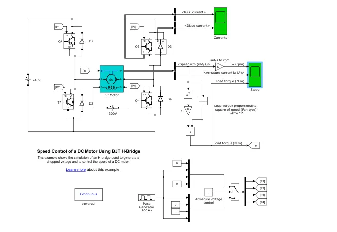
Model Discription :
1. DC motor is used to present (5 HP 24 V 1750rpm). It simulates a fan type load (where load torque is proportional to square of speed). The armature mean voltage can be varied from 0 to 240 V when the duty cycle (specified in the pulse Generator block) is varied from 0 to 100%.
2. The H-bridge consists of four BJT/Diode pairs (BJT simulated by IGBT models).
3. Two transistors are switched simultaneously : Q1 and Q4 or Q2 and Q3. When Q1 and Q4 are fired, a positive voltage is applied to the motor and diodes D2-D3 operate as free-wheeling diodes when Q1 and Q4 are switched off.
4. When Q2 and Q3 are fired, a '-ve' voltage is applied to the motor an ddiodes D1-D4 operate as free-wheeling diodes when Q2 and Q3 are switched off.
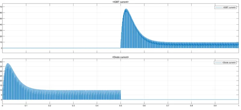
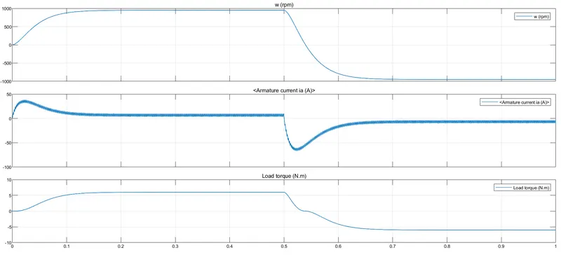
Simulation Results :
CASE 2 :
B. Comment on the armature current shoot-up from the scope results.
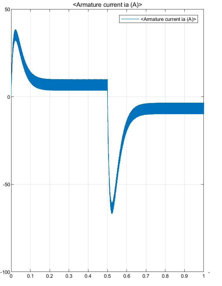
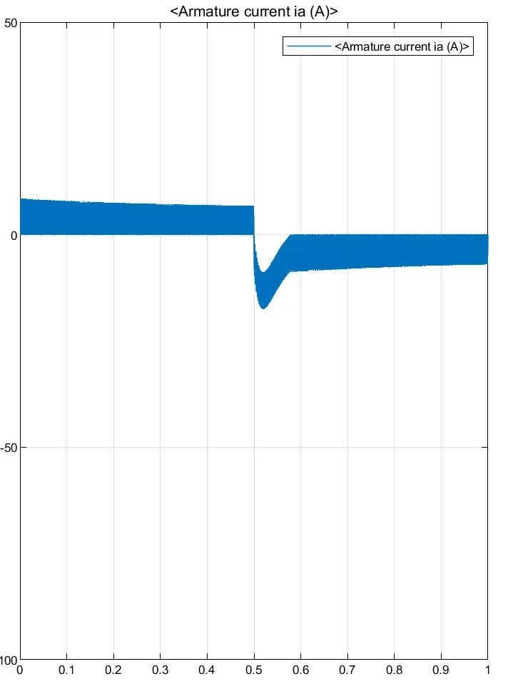
From armature current graph, we can see that, at starting there is a sudden spike increase in current at 0 sec and at 0.5 sec also means at transition from '+ve' to '-ve' direction of rotation we observe a high surge in current, this is due to the transient switching occuring in the circuit.
As there is already current flowing in the circuit and on changing of switches after 0.5 sec, the current in the circuit adds to the changed direction of current and we odserve a surge in current.
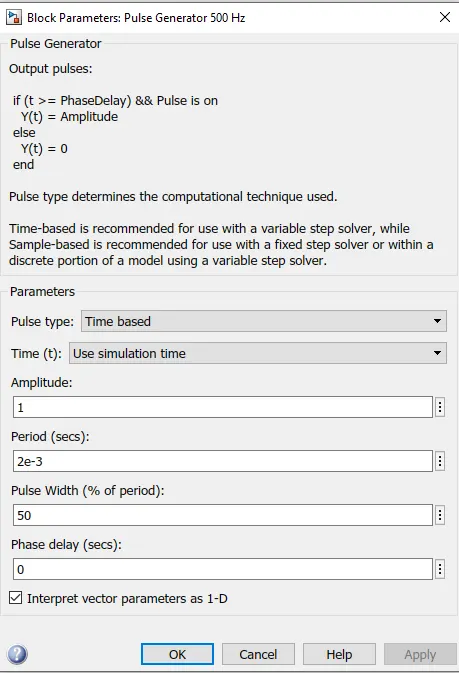
The surge in the current can be reduced by reducing the duty cycle. In above result the duty cycle is 75%. Now, changing the duty cycle from 75% to 50%, the current surge can be reduced tremendously as :
CASE 3 :
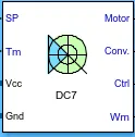
C. Refer to the help section of ‘The Four-Quadrant Chopper DC Drive (DC7) block’. Compare it with the H-bridge model.
Working of four quadrant chopper :
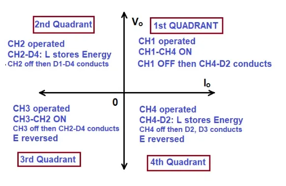
The circuit of a four quadrant chopper or class-E chopper basically consists of four semicondutor switches CH1 to CH4 an dfour diodes D1 and D4. The four diodes are connected in anti-parallel. The circuit diagram of this type of chopper is shown below :
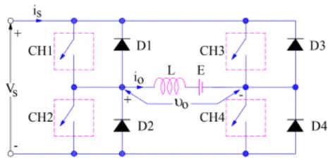
In above circuit diagram, the chopper are numbered CH1 to CH4. For first quadrant operation CH1 is made ON, for second quadrant operation CH2 is made ON and so on. To better understand this, we will see the below diagram as :
Comparison of 4 quadrant chopper and BJT H-Bridge :
1. 4 quardant chopper works in all four modes as :
A. Forward motoring
B. Forward breaking
C. Reverse motoring
D. Reverse breaking
But, BJT H-Bridge model works only on two modes as :
A. Forward motoring
B. Reverse motoring
2. To change the direction of rotation of motor from forward to reverse and vice-versa, the current signals get transited from one to other switch while in H-Bridge model, the direction of rotation of motor is changed by changing the polarity of current.
3. The 4 quadrant chopper have high switching frequency, while H-Bridge model have low switching frequency.
4. The armature current in 4 quadrant chopper have a little spike at transition from one to other switch because of high switching frequency, while H-Bridge model have high spike of current.
5. The 4 quadrant choppers is generally used in industrial application, while H-Bridge model is used in robotics.
ANS 2 :
2. Develop a 2-quadrant chopper using simulink & explain the working of the same with the relevant results. (Refer to article - Multiquadrant operation of motor )
CKT DIAGRAM OF 2-QUADRANT CHOPPER :
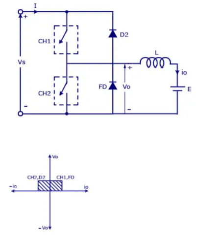
Two quadrant chopper is also called as type 'C' chopper. Type 'C' chopper is obtained by connecting type-A and type-B choppers in parallel. We will always get a '+ve' output voltage 'Vo' as a free-wheeling diode 'FD' is present across the load. When the chopper is on the free-wheeling diodes start conducting and output voltage 'Vo' will be equal to 'Vs'. The direction of the load current 'io' will be reversed. The current 'io' will be flowing towards the source and it will be '+ve' regardless the chopper is on or FD conducts. The load current will be '-ve' if the chopper is or the diode D2 conducts. We can say that chopper and FD operate together as type-A chopper in first quadarant, in second quadrant the chopper and D2 will operate together as type-B chopper.
MATLAB MODEL :
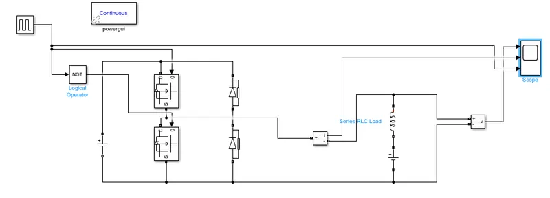
Let us take two mosfet blocks and diodes blocks and connect it as shown in ckt diagram, the DC voltage source is connected as shown :
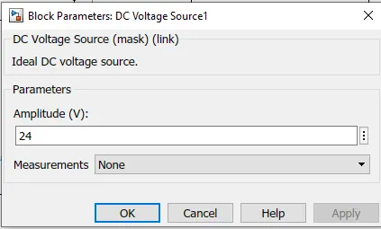
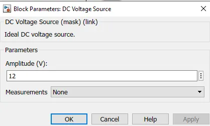
Let the voltage of DC voltage soucrce be 24 volts.
Let us consider an series RLC branch block and select inductor L. Thus, block works as a load to consider LE load i.e motor load, and dc voltage source of 12 volts is also connected in series with inductor as :
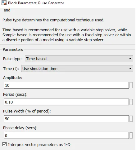
The pulse generator block is used to create pulse. The not gate is used in the model so that the two MOSFET will not get closed at the same time otherwise short ckt will occur due to of not gate, when one MOSFET will get off and when other MOSFET is on, the first MOSFET will get off.
The amplitude of pulse generator is kept 10 so that we can clearly see the pulses at scope and let period be 0.10 seconds and let pulse width be 50% as :
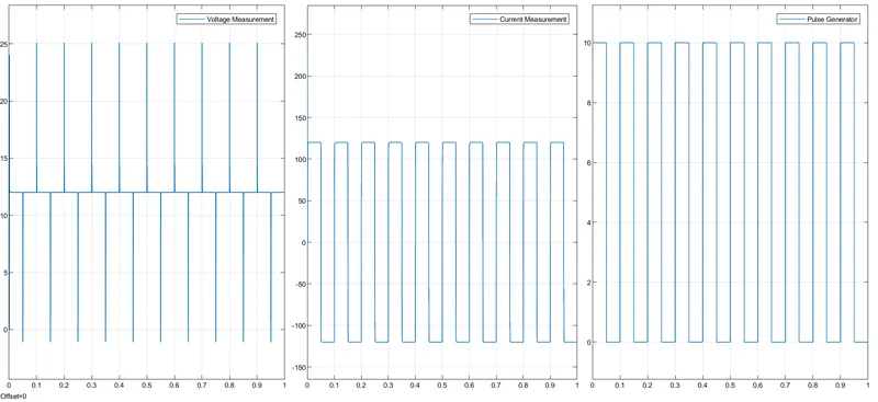
SIMULATION RESULTS :
ANS 3 :
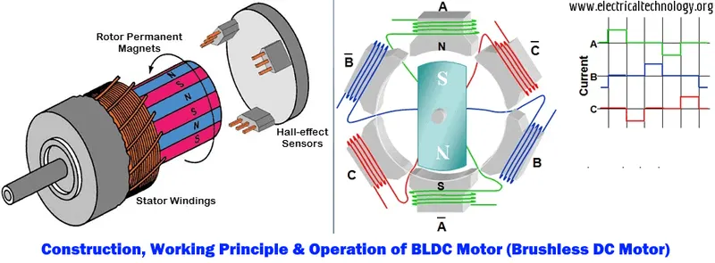
3. Explain in a brief about operation of BLDC motor.
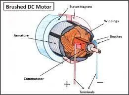
A Brushless DC Electric Motor (BLDC) is an electric motor powered by a direct current voltage supply and commutated electronically instead of by brushes like in conventional DC motors.
OPERATION :
BLDC motor works on the principle similar to that of a Brushed DC motor. The Lorentz force law which states that whenever a current carrying conductor placed in a magnetic field it experiences a force. As a consequence of reaction force, the magnet will experience an equal and opposite force.
Advantages of BLDC motor :
1. Less overall maintenance due to absence of brushes.
2. Reduced size with far superior thermal characteristics.
3. Higher speed range and lower electric noise generation.
4. It has no mechanical commutator and associated problems.
5. High efficiency and high power output to size ratio due to the use of permanent magnet rotor.
6. High speed of operation even in loaded and unloaded conditions due to the absence of brushes that limits the speed.
Disadvantages :
1. These motors are costly.
2. Electronic controller required control this motor is expensive.
3. Requires complex drive circuitry.
4. Need of additional sensors.