Week - 4
Ans 1:
Aim :
- Implement control logic of a “washing machine” using Stateflow as per given sequence:
- If the power supply is available, the system gets activated
- If the Water supply is not available, stop the process & indicate through LED
- Soaking time should be 200s followed by Washing time of 100s.
- Then rinsing happens for next 20s & dryer runs for 50s
After all the processes have completed turn on the finished LED
2. Make a Simulink chart for the “Gear shift” logic as per below conditions:
Speed Range(kmph) Gear
0 to 15 1
16 to 25 2
26 to 40 3
41 to 60 4
Above 61 5
Give speed input while the simulation is running & display the gear number.
Solution 1:
- Implement control logic of a “washing machine” using Stateflow as per given sequence:
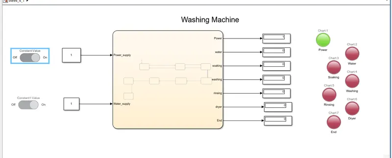
- If the power supply is available, the system gets activated
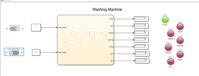
- If the Water supply is not available, stop the process & indicate through LED
- Soaking time should be 200s followed by Washing time of 100s.
- Then rinsing happens for next 20s & dryer runs for 50s
A washing machine (laundry machine, clothes washer, washer, or simply wash) is a home appliance used to wash lanundry The term is mostly applied to machines that use water as opposed to dry cleaning (which uses alternative cleaning fluids and is performed by specialist businesses) . The user adds lanundry ditergent which is sold in liquid or powder form, to the wash water.
Modeling of washing machine in simulink:
these are the following things we need to the subsystem of washing machine :
1. Slider switch
2. Constant
3. State flow chart
4. Lamps
5. Diplay
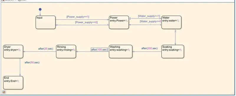
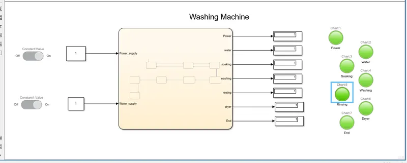
Now, will go through step by step.
1. If the power supply is available, the system gets activated as below:
2. If the Water supply is not available, stop the process & indicate through LED as under:
3. Soaking time should be 200s followed by Washing time of 100s:
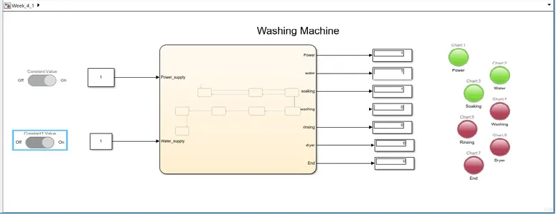
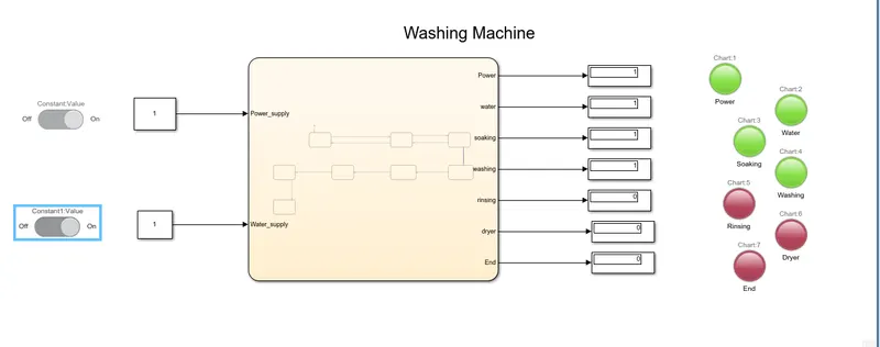
4. Then rinsing happens for next 20s & dryer runs for 50s:
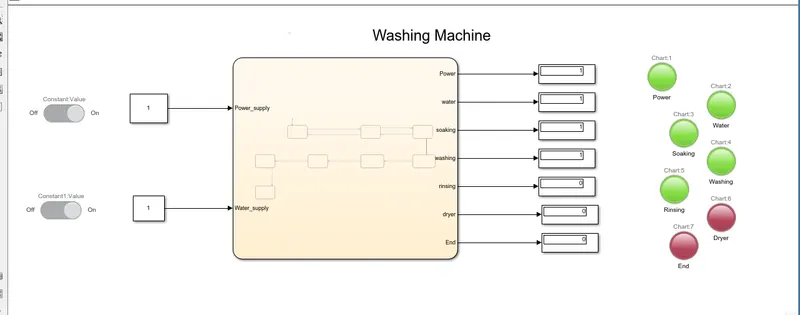
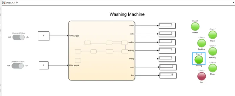
and that's how we did the washing machine simulink. As we see the lamps is lit accordingly .
Solution 2 :
2. Make a Simulink chart for the “Gear shift” logic as per below conditions:
Speed Range(kmph) Gear
0 to 15 1
16 to 25 2
26 to 40 3
41 to 60 4
Above 61 5
Give speed input while the simulation is running & display the gear number.
The gears determine the amount of power available from the engine. First gear provides the most pulling power but the least potential for speed, whilst fifth gear which provides the least pulling power allows the greatest range of speed.
Modeling of Gear shift in simulink:
these are the following things we need to the subsystem of Gear shift:
1.State flow chart
2. Lamps
3. Diplay
4. Slider
5. Constant
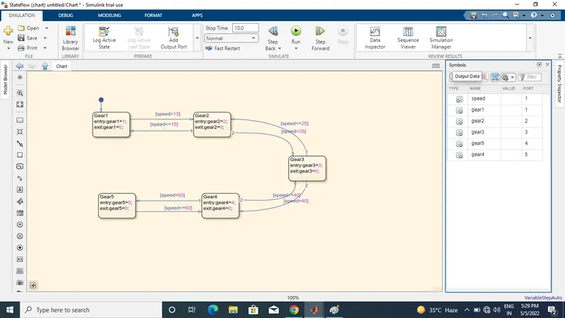
Now, we move as per given data :
1. Speed Range(kmph) Gear
0 to 15 1
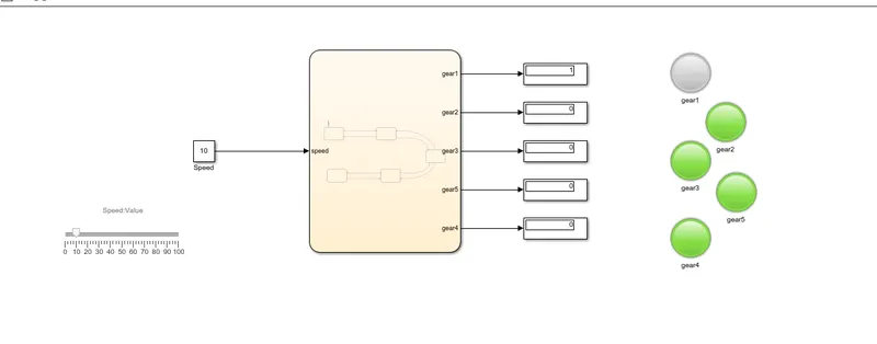
2. Speed Range(kmph) Gear
16 to 25 2
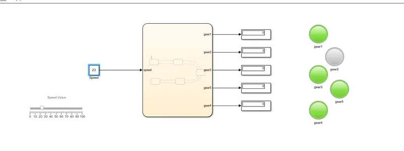
3. Speed Range(kmph) Gear
26 to 40 3
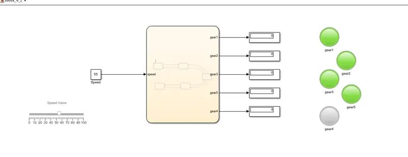
4. Speed Range(kmph) Gear
41 to 60 4
5. Speed Range(kmph) Gear
Above 61 5
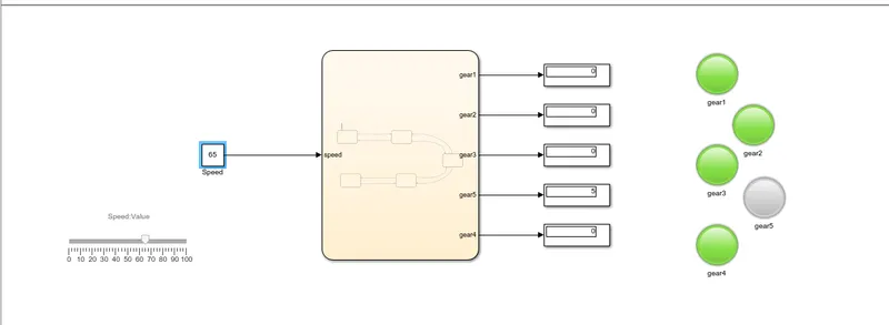
and that's how we did the gear shift logic in simulink. As we see the lamps is lit accordingly to gear it.