Week-7 Challenge: DC Motor Control
Answer:
1. A. Explain a MATLAB demo model named ‘Speed control of a DC motor using BJT H-bridge'
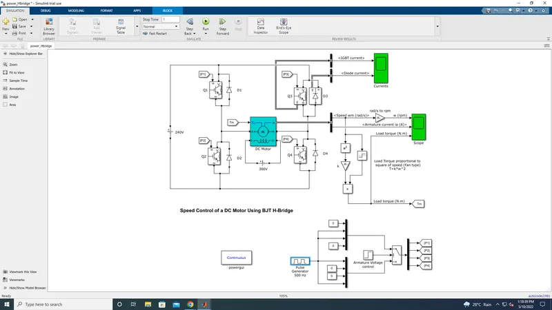
In the MATLAB/SIMULINK documentation, we can search for the simulation model of the 'Speed control of a DC Motor using BJT H[1]bridge'. It is used to generate a chopped voltage and to control the speed of the DC motor. This model can be opened in SIMULINK
from the documentation itself. As the name suggests, it uses a BJT (Bipolar Junction Transistor which is a type of transistor that uses
both electrons and holes as charge carriers, hence the name bipolar. Other transistors such as FETs (Field Effect Transistors) are
unipolar transistors meaning that they only use one type of charge carrier. BJTs are used for switching and amplifying applications.
BJTs have 3 terminals which are: the emitter (E), the base (B) and the collector (C). Current flows in only the emitter and the collector
and the amount of current that flows through them is controlled by the base. BJTs use semiconductors in their working, and so there
are 2 types of BJT: NPN type and PNP type
The Bipolar Junction Transistor when used for power switching applications, operates as an IGBT. When it is conducting (BJT operating
in the saturated region), a forward voltage Vf is developed between collector and emitter (in the range of 1 V). Therefore, the IGBT
block can be used to model the BJT device.
The IGBT block does not simulate the gate current controlling the BJT or IGBT. The switch is Controlled by a Simulink signal (1/0).
The DC motor uses the preset model (5 HP 24V 1750 rpm). It simulates a fan type load (where Load torque is proportional to square
of speed). The armature mean voltage can be varied from 0 to 240 V when the duty cycle (specified in the Pulse Generator block) is
varied from 0 to 100%.
PNP Transistor
This type uses 2 p-type semiconductors and one n-type semiconductor. The n-type semiconductor will be the base of the transistor.
The emitter terminal is more positive in relation to the collector and base terminals. The collector is connected to positive supply and
emitter is connected to negative supply. The base terminal is supplied with voltage and it operates the transistor by switching
between ON or OFF states. When the base voltage is the same as the emitter voltage, the transistor is in the OFF state. When the base
voltage decreases with respect to the emitter voltage, The transistor is in the ON state.
NPN Transistor
This type uses 2 n-type semiconductors and one p-type semiconductor. The p-type semiconductor will be the base of the transistor.
Construction wise it is exactly the same as the PNP type having 3 terminals. Just as in the PNP type, the collector terminal is conneced
to the positive voltage supply and the emitter terminal is connected to the negative voltage supply. The base terminal is supplied with
a voltage and controls the transistor being either in an ON or OFF state. When the base voltage is the same as the emitter voltage, the
transistor will be in the OFF state. When the base voltage increases with respect to the emitter voltage, the transistor will be in the ON state
BJT H-Bridge
When the BJT is conducting i.e. operating in the saturated region, there will be a forward voltage developed between the collector and
the emitter (in the range of 1V). An IGBT is used to model the BJT because of this. The switch is controlled by a SIMULINK signal. The DC
motor used in this model is preset to with specifications: 5HP, 24V, 1750rpm. It simulates a fan type load where the load is proportional
to the square of the speed. The mean armature voltage can be varied between 0 and 240V when the duty cycle is changed
anywhere from 0 to 100%. The duty cycle can be changed from the pulse generator block
The H-bridge consists of four BJT/Diode pairs (BJT simulated by IGBT models). Two transistors are switched simultaneously: Q1 and
Q4 or Q2 and Q3. When Q1 and Q4 are fired, a positive voltage is applied to the motor and diodes D2-D3 operate as free-wheeling
diodes when Q1 and Q4 are switched off. When Q2 and Q3 are fired, a negative voltage is applied to the motor and diodes D1-D4
operate as free-wheeling diodes when Q2 and Q3 are switched off.
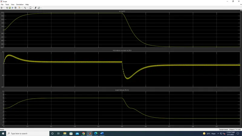
When the simulation is run the motor starts in the positive direction with a duty cycle ratio75% ( pulse generator). At t = 0.5 sec the armature voltage is
suddenly reversed and the motor runs in the negative direction.
Scope shows the motor speed, armature current and load torque.
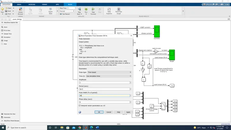
And now run the model, with the duty cycle 50%. ( pulse generator)
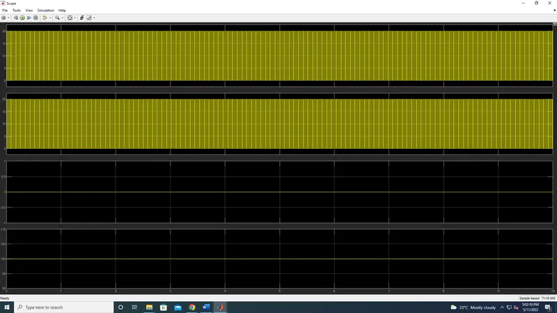
Scope shows the motor speed, armature current and load torque
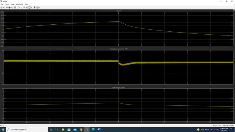
As we change the Duty cycle percentage speed, amarture current, load torque varies as per the percentaage varies in the duty cycle
If we change the Duty cycle the diode current and IGBT current is changes
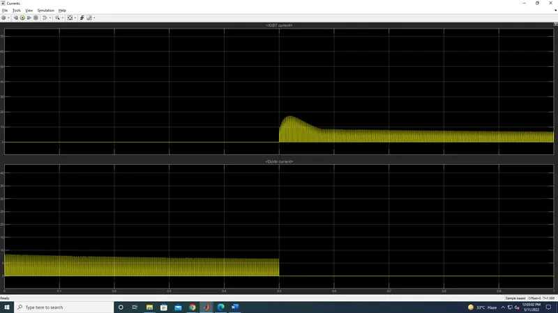
Refer to the help section of ‘The Four-Quadrant Cho
pper DC Drive (DC7) block’. Compare it with the H-bridge model
The Four-Quadrant Chopper DC Drive (DC7) block
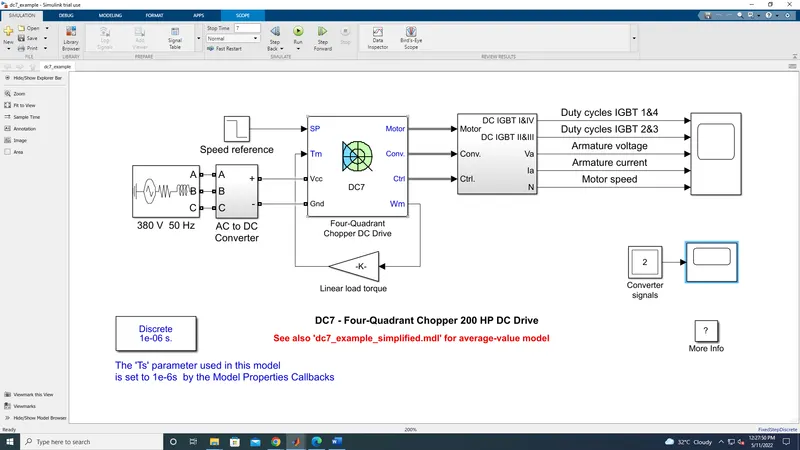
The four quadrant chopper DC drive block in MATLAB/SIMULINK represents a four quadrant, DC supplied chopper drive for DC motors.
It is also referred to as the 'DC7' motor drive in SIMSCAPE. It features closed loop speed control with four quadrant operation. The
closed loop speed control will output the armature current of the machine. Using a PI current controller, the chopper duty cycle
corresponding to the commanded armature current is derived. The duty cycle is then compared with a sawtooth carrier signal to
obtain the required PWM signals for the chopper.
Compared to other DC drives, the main advantage of using the four quadrant chopper DC drive is that it can operate in all 4
quadrants. Each quadrant in its characteristics represents a different mode of operation. The first quadrant is forward motoring, the
second is reverse braking, the third is reverse motoring and the forth is forward braking. Another advantage is that it uses high
switching frequency DC-DC converters resulting in a lower armature current ripple is occurs than compared to thyristor based DC drives
The four quadrant chopper DC drive uses these 4 main blocks from the fundamental drive blocks library:
1. speed controller
2. current controller
3. regulation switch
4. chopper
working Operation of four Quadrant
Forward Motoring: motor rotates clockwise and controller applies a clockwise drive.
Reverse Motoring: motor rotates anti-clockwise and controller applies an anti-clockwise drive.
Forward Braking: motor rotates clockwise and controller applies anti-clockwise drive.
Reverse Braking: motor rotates anti-clockwise and controller applies a clockwise drive.
The screenshot the scope has been attached below.
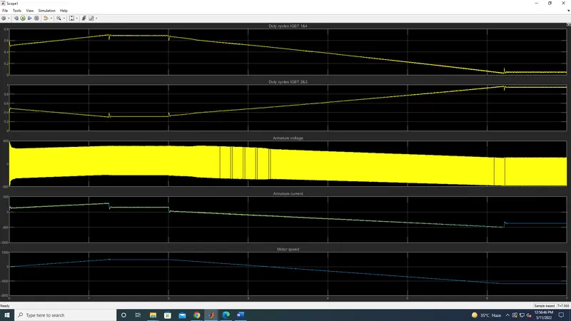
The screenshot of scope output by using the converter reference
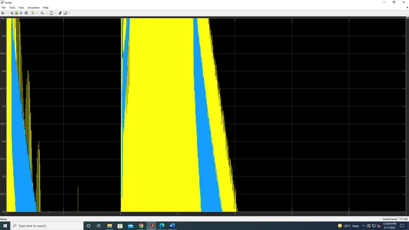
Compare it with the H-bridge model
Output of speed, Amarture, load
output of diode and IGBT current
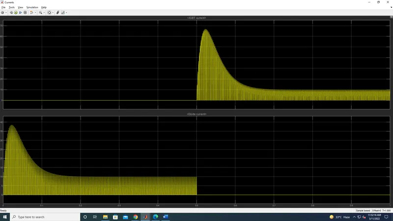
3. Explain in a brief about operation of BLDC motor.
Brushless DC Motor (BLDC)
Brushless DC motors (BLDC) have been a much focused area for numerous motor manufacturers as these motors are increasingly the preferred choice in many applications, especially in the field of motor control technology. BLDC motors are superior to brushed DC motors in many ways, such as ability to operate at high speeds, high efficiency, and better heat dissipation.
They are an indispensable part of modern drive technology, most commonly employed for actuating drives, machine tools, electric propulsion, robotics, computer peripherals and also for electrical power generation. With the development of sensorless technology besides digital control, these motors become so effective in terms of total system cost, size and reliability.
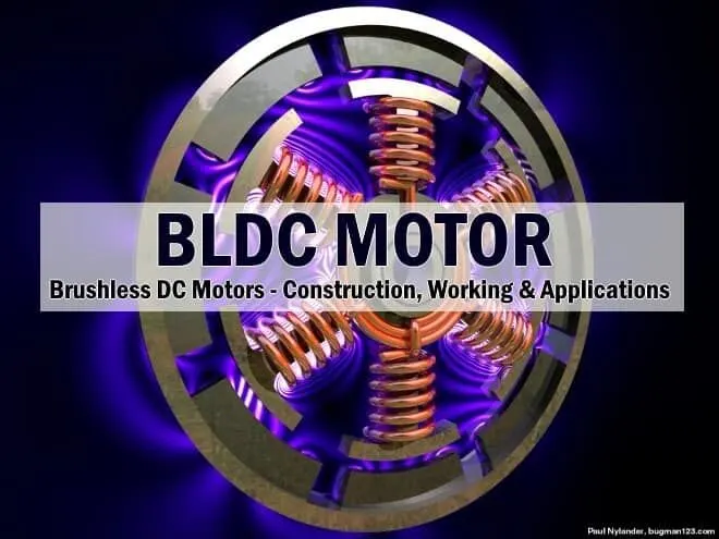
A brushless DC motor (known as BLDC) is a permanent magnet synchronous electric motor which is driven by direct current (DC) electricity and it accomplishes electronically controlled commutation system (commutation is the process of producing rotational torque in the motor by changing phase currents through it at appropriate times) instead of a mechanically commutation system. BLDC motors are also referred as trapezoidal permanent magnet motors.
Unlike conventional brushed type DC motor, wherein the brushes make the mechanical contact with commutator on the rotor so as to form an electric path between a DC electric source and rotor armature windings, BLDC motor employs electrical commutation with permanent magnet rotor and a stator with a sequence of coils. In this motor, permanent magnet (or field poles) rotates and current carrying conductors are fixed.
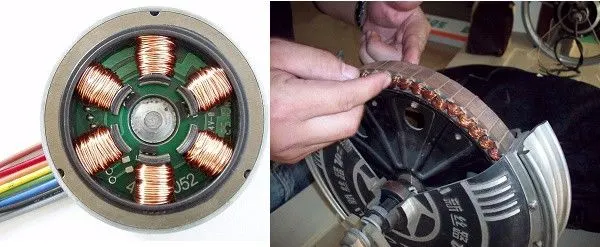
The armature coils are switched electronically by transistors at the correct rotor position in such a way that armature field is in space quadrature with the rotor field poles. Hence the force acting on the rotor causes it to rotate. Hall sensors or rotary encoders are most commonly used to sense the position of the rotor and are positioned around the stator. The rotor position feedback from the sensor helps to determine when to switch the armature current.
This electronic commutation arrangement eliminates the commutator arrangement and brushes in a DC motor and hence more reliable and less noisy operation is achieved. Due to the absence of brushes BLDC motors are capable to run at high speeds. The efficiency of BLDC motors is typically 85 to 90 percent, whereas as brushed type DC motors are 75 to 80 percent efficient. There are wide varieties of BLDC motors available ranging from small power range to fractional horsepower, integral horsepower and large power ranges.
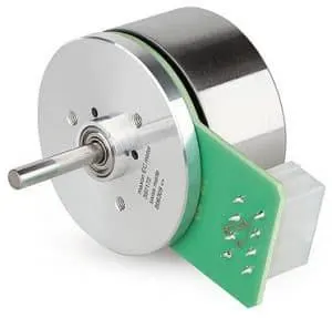
BLDC motors can be constructed in different physical configurations. Depending on the stator windings, these can be configured as single-phase, two-phase, or three-phase motors. However, three-phase BLDC motors with permanent magnet rotor are most commonly used.
The construction of this motor has many similarities of three phase induction motor as well as conventional DC motor. This motor has stator and rotor parts as like all other motors
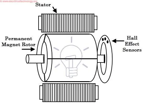
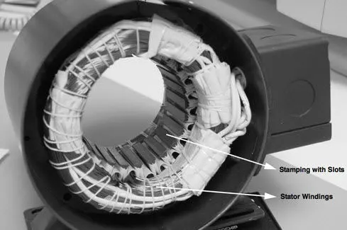
Stator of a BLDC motor made up of stacked steel laminations to carry the windings. These windings are placed in slots which are axially cut along the inner periphery of the stator. However, most BLDC motors have three phase star connected stator.
Each winding is constructed with numerous interconnected coils, where one or more coils are placed in each slot. In order to form an even number of poles, each of these windings is distributed over the stator periphery.
Brushless DC Motor Drive
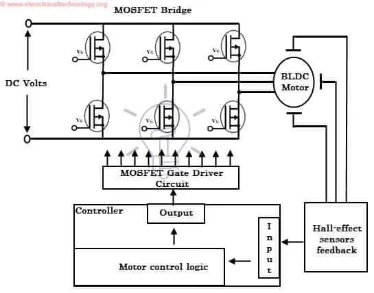
As described above that the electronic controller circuit energizes appropriate motor winding by turning transistor or other solid state switches to rotate the motor continuously. The figure below shows the simple BLDC motor drive circuit which consists of MOSFET bridge (also called as inverter bridge), electronic controller, hall effect sensor and BLDC motor.
Here, Hall-effect sensors are used for position and speed feedback. The electronic controller can be a microcontroller unit or microprocessor or DSP processor or FPGA unit or any other controller. This controller receives these signals, processes them and sends the control signals to the MOSFET driver circuit.
In addition to the switching for a rated speed of the motor, additional electronic circuitry changes the motor speed based on required application. These speed control units are generally to have precise control. It is also possible to produce four-quadrant operation from the motor whilst maintaining good efficiency throughout the speed variations using modern drives.
Applications of Brushless DC Motors (BLDC)
Computer hard drives and DVD/CD players
Electric vehicles, hybrid vehicles, and electric bicycles
Industrial robots, CNC machine tools, and simple belt driven systems
Washing machines, compressors and dryers
Fans, pumps and blowers
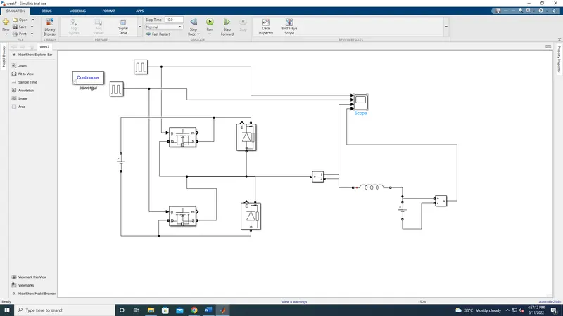
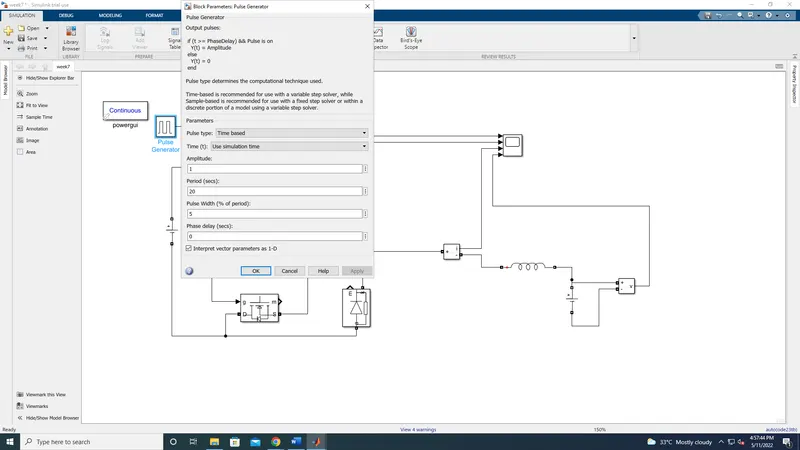
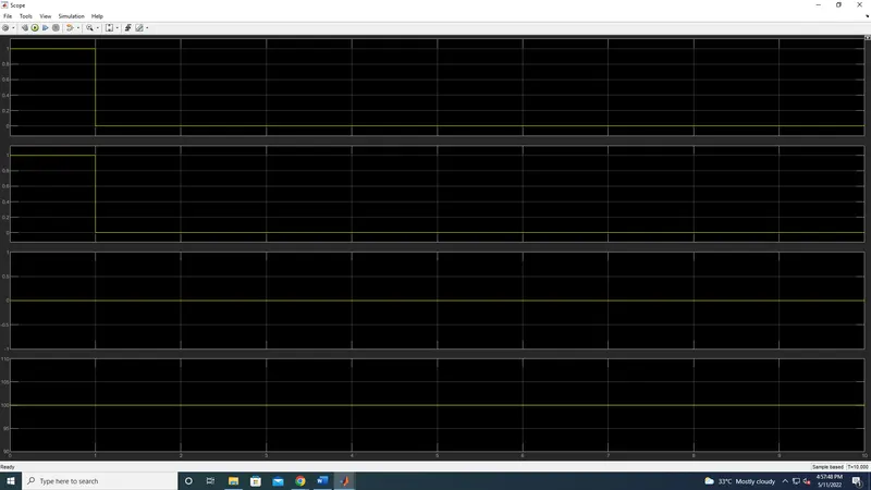
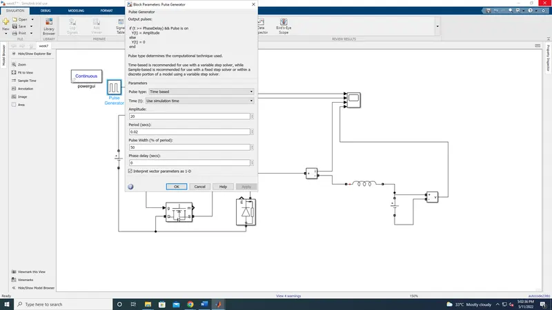
3.Develop a 2-quadrant chopper using simulink & explain the working of the same with the relevant results. (Refer to article - Multiquadrant operation of motor )
Answer: