Project 1 (Mini Project on Vehicle Direction Detection
Answer: MINI-PROJECT
Objective
> The objective of this project is to develop a MBD compliant MATLAB Simulink model for vehicle direction detection as per the given
requirement.
> Tag the requirements to the Simulink model, Requirements 1 & Requirement 2 are tagged into their corresponding subsystems.
Make necessary MBD complilant changes.
> Creating of Simulink Data Dictionary (SLDD) for the given model.
> Choose sample time for all signals as 0.01 sec.
> Creation of test harness to Perform Model In Loop (MIL) test.
Procedure:
> At first need to open a simulink page and creat two inport, one outport along with subsystem.
> Name the two inport as streeingwheel_yawdegreeinput and camerainput_roadsign
And outport as vehicle_direction_indicator
> Name the subsystemm as vehicle_direction
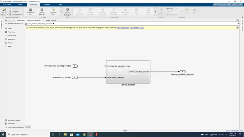
Now double click on the subsystem,
Then create two system and name it as Requirement-1 and Requirement-2
Connect the streeing1 to requirement-1 and cmaerainput to requirement-2
And the outport remains same as vehicle_direction_indicator.
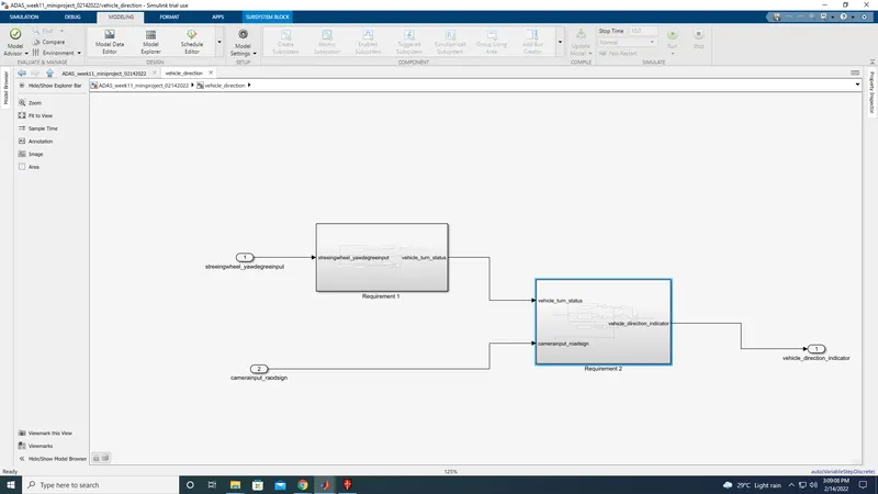
Now double click on requirement-1
now we need to asign the block as per the conditons
- Steering wheel input as yaw rate (Signal name: SteeringWheel_YawDegreeInput) is the input for this system.
- This is compared against 3 angular values, one each for left turn, right turn & straight drive (Calibration Values: Right_Turn_AngularLimit, Left_Turn_AngularLimit, Straight_Drive_Steering_Angle) to say which specific direction the steering wheel is turning towards.
- Use switch blocks to compare & develop this requirement. Keep this requirement in a subsystem & output of this requirement is a local signal (Signal Name: Vehicle_Turn_Status).
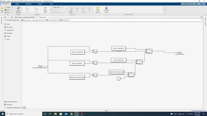
> In this Requirement1 subsystem, the steering wheel yaw degree is given as input to the
subsystem and this input value is compared against 3 angular values, one each for left turn, right turn & straight drive to tell the steering wheel is turning towards
which direction.
> In this case, the output of the relational operator '==' is equal to 1 only when the 'SteeringWheel_YawDegreeInput' matches with any one
of caliberation value then it will give logical 1 or
true condition
> Three signal switch blocks are used to implement an if-else logic. The output from each relational operator(==) is given to second port
of each switch block. The switch will pass input1 when the condition condition is satisfied, else
input3 is passed as output..
> If 'SteeringWheel_YawDegreeInput' does not matches with any one of caliberation value then it will give logical 0 or false condition. Then, it will take the value
mentioned in the third port of switch 3. In this case, at the third port, value mentioned is 0 hence, the same is given out as output
Requirement- 2(subsystem)
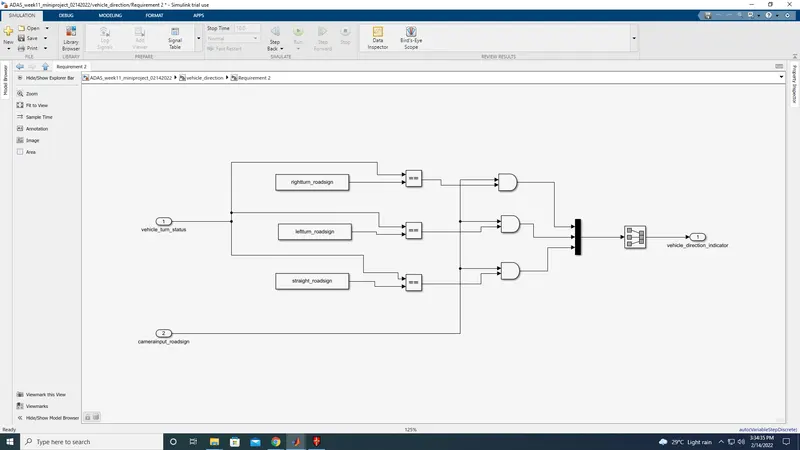
> In 'Requirement2' subsystem, the local signal 'Vehicle_Turn_Status' is fed from 'Requirement1' subsystem and given as an input and is
compared against calibration values using the relational operator '=='
> If the value matches, then the relational operator (==) gives logical 1 or true value and same is compared in AND operation with input
signal from camera i.e.CameraInput_RoadSign which states that when camera actually captures the road sign, then it is compared with
caliberation value of road sign values and when it matches, then
only output signal is provided in the form of boolean values.
> The output 'Vehicle_Direction_Indicator' will be a three dimension signal having three boolean elements, with the first element to
indicate 'Right Turn', second element to indicate 'Left Turn' and third element to indicate 'Straight Drive'.
> Since, signals such as Vehicle_Turn_Status is already being used in this model hence we proporgate the same signal by clicking on signal
and entered '<>'.
Hence the subsystem been arranged as per the given condition.
Now need to add the data dictionary.
and the values been given in the question
Signals & Calibration Data List:
|
Signal / Calibration Name |
Signal Type |
Data Type |
Dimension |
Min |
Max |
Initial Value |
Units |
|
SteeringWheel_YawDegreeInput |
Input |
Int16 |
1 |
-180 |
180 |
- |
Deg |
|
CameraInput_RoadSign |
Input |
Boolean |
1 |
0 |
1 |
- |
- |
|
Vehicle_Turn_Status |
Local |
Int16 |
1 |
-180 |
180 |
- |
Deg |
|
Right_Turn_AngularLimit |
Calibration |
Int16 |
[1 1] |
-180 |
180 |
30 |
Deg |
|
Left_Turn_AngularLimit |
Calibration |
Int16 |
[1 1] |
-180 |
180 |
-120 |
Deg |
|
Straight_Drive_Steering_Angle |
Calibration |
Int16 |
[1 1] |
-180 |
180 |
0 |
Deg |
|
RightTurn_RoadSign |
Calibration |
Int16 |
[1 1] |
-180 |
180 |
30 |
|
|
LeftTurn_RoadSign |
Calibration |
Int16 |
[1 1] |
-180 |
180 |
-120 |
|
|
Straight_RoadSign |
Calibration |
Int16 |
[1 1] |
-180 |
180 |
0 |
|
|
Vehicle_Direction_Indicator |
Output |
Boolean |
1 |
0 |
1 |
- |
- |
now need to add these signals into data dictionary.
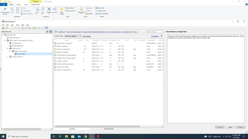
Before that click on modeling tab and click on model setting and select
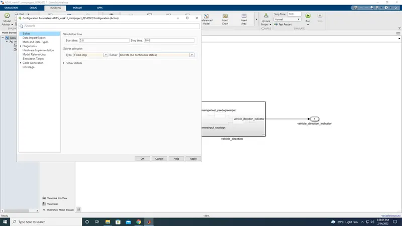
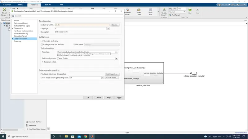
now click on link to data dictonary to add the signals
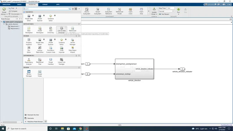
now save the signals.
To perfom the Model in loop test (Mil).
right click on the subsystem select test harness and click on create for vehicle_direction
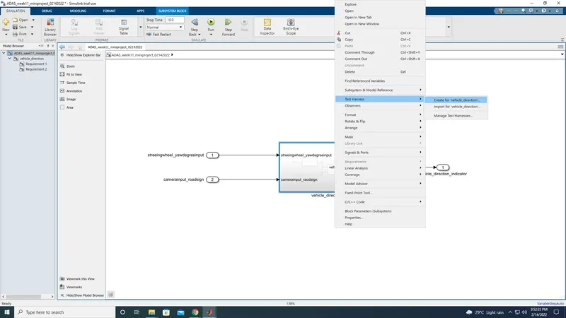
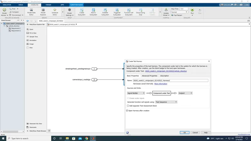
Then the new tab will be open
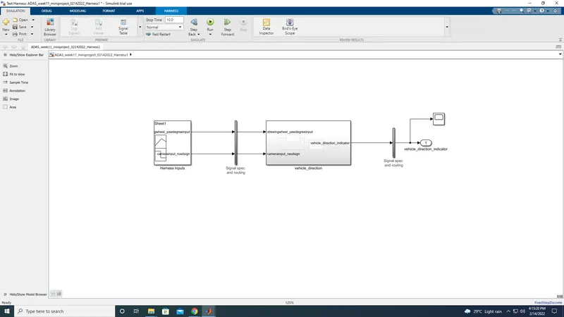
in that double click on signal builder
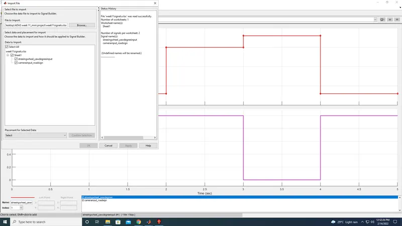
Now add the scope in the outport to see the output in the graphical exprission.
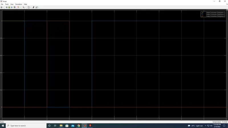
Thus the mini project been completed by performing the Model in loop test (mil)