Week-7 Challenge: DC Motor Control
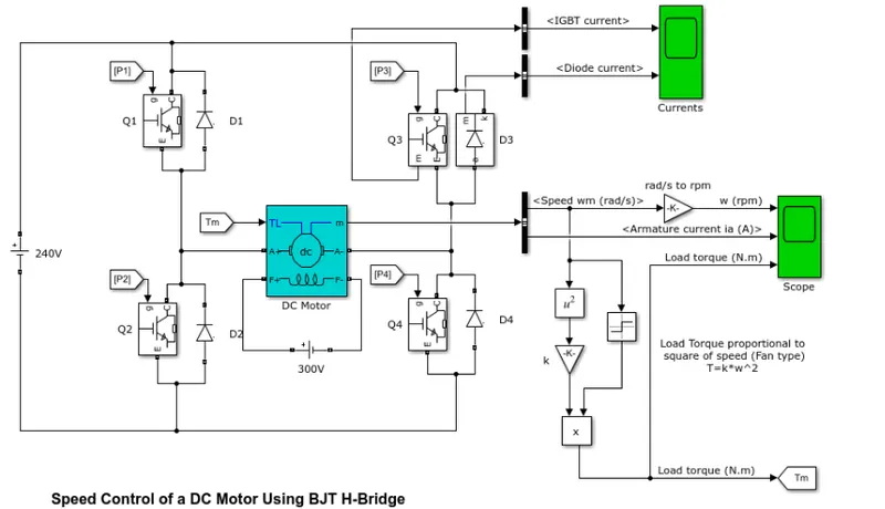
A. Explain a MATLAB demo model named ‘Speed control of a DC motor using BJT H-bridge’.
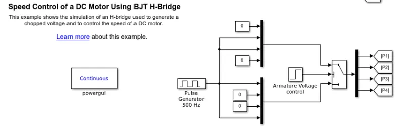
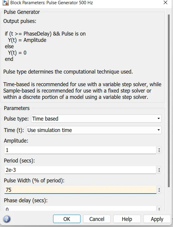
default value of pluse generator
H Bridge is a simple electronic circuit which enables us to apply voltage to load in either direction. It is commonly used in robotics application to control DC Motors. By using H Bridge we can run DC Motor in clockwise or anticlockwise directions. This circuit is also used to produce alternating waveforms in inverters.
Freewheeling diodes are special type of diodes
These are also called by many other names like snubber diode, suppressor diode, catch diode or clamp diode, commutating diode. Here catch diode is used to eliminate flyback, when the abrupt voltage spike is witnessed across the inductive load when the supply current abruptly reduced. It helps the circuit from damaging.
basically this type of diodes of zener diodes, in this case when spike or high voltage appear in circuit that diode go open immediately with a low resistance resulting inductive and resistive components are go isolated, from heavy power pressure thus offer spike (high voltage) protection
Simulation
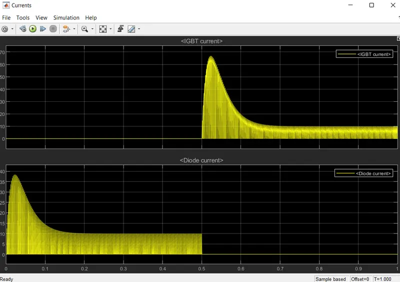
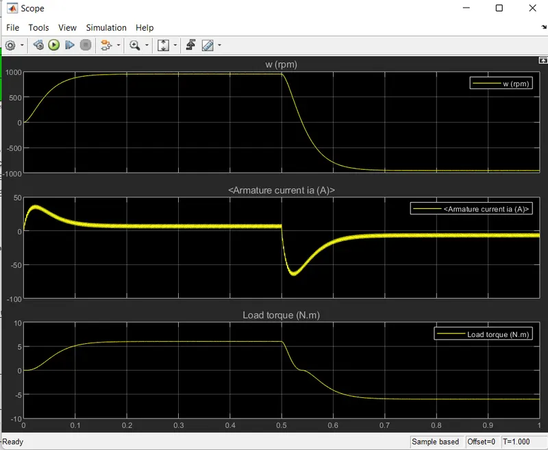
The motor starts in the positive direction with a duty cycle of 75% (mean DC voltage of 180V). At t= 0.5 sec., the armature voltage is suddenly reversed and the motor runs in the negative direction.
'Scope' shows motor speed, armature current and load torque and 'Currents' shows currents flowing in BJT Q3 and diode D3.
B. Comment on the armature current shoot-up from the scope results.
an Armature
An armature is defined as the component of an electric machine (i.e. a motor or generator) that carries alternating current (AC). The armature conducts AC even on DC (Direct Current) machines via the commutator (which periodically reverses current direction) or due to electronic commutation, (e.g. in a brushless DC motor).
The armature provides housing and support to the armature winding. In electrical machines, the magnetic field is generated by a permanent magnet or electromagnet. The armature winding interacts with the magnetic field formed in the air gap. The stator can be a rotating part (rotor) or stationary part (stator).
Armature Work?
An armature is used as an electric motor or generator. The armature is used to communicate between two magnetic fluxes.
When the armature is used as an electric motor, due to relative motion between flux produced by the field winding and the flux produced by the armature winding the EMF is induced.
This EMF will oppose the current of an armature and the torque produced in the rotor. And hence, the electrical power is converted into mechanical power. The toque produced in the rotor is transferred to rotate other devices via a shaft.
When the armature is used as an electric generator, in most cases the armature used as a rotor. And the armature was driven mechanically with the help of diesel engine or prime mover.
The field winding is excited to generate a magnetic field. The armature EMF drives the armature current and hence, the mechanical power of shaft is converted into electrical power.
Armature Parts & Diagram
The armature is made up of a core, winding, commutator, and shaft. A diagram of an armature is shown below.
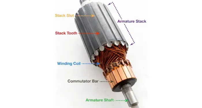
The parts of an armature are discussed in detail below.
Armature Core
The core of the armature is made up of laminated thin metal plates instead of a single piece. The thickness of laminations depends on the supply frequency. It is approximately 0.5mm thick. The laminated silicon steel is used for the armature core to reduce the eddy current and hysteresis loss.
Generally, the armature core is a hollow cylindrical shape. And the shaft is placed inside the armature core.
The core consists of the number of slots. The armature winding is placed in the slots provided on the outer surface of the armature core. The slots in the armature core are skewed at some angle to avoid magnetic locking and provides smooth rotation.
given that motor specification
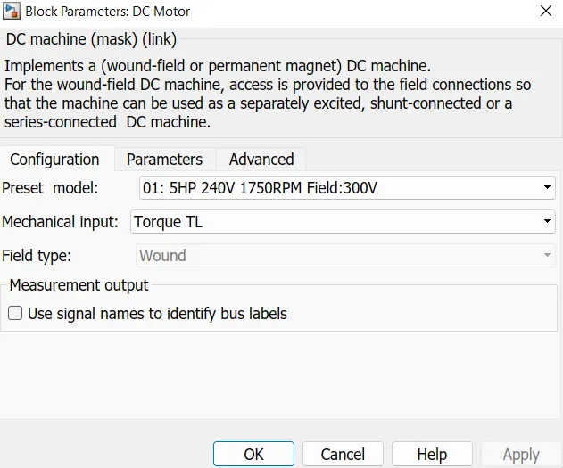
if we noticed that after changing the default value from 75 % to 45%.
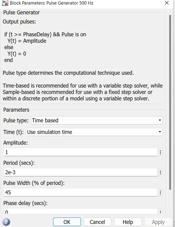
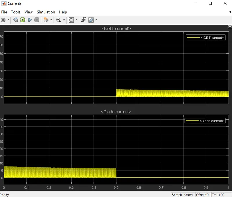
there is a peak when the motor is switching direction , then the duty cycle is future reduced to 45% then following plot shows :
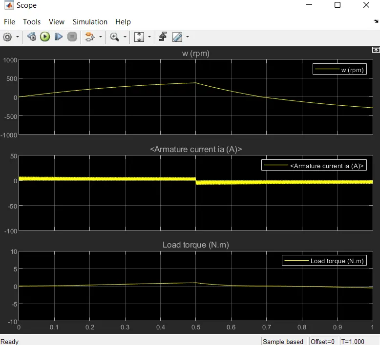
after set it 40-45% there is no sudden peak changed show in output .
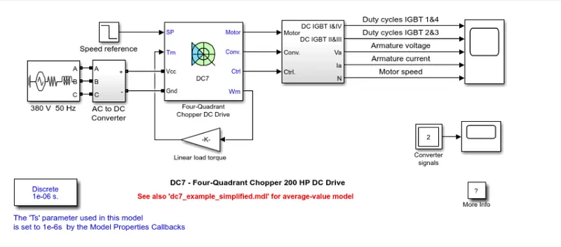
C. Refer to the help section of ‘The Four-Quadrant Chopper DC Drive (DC7) block’. Compare it with the H-bridge model.
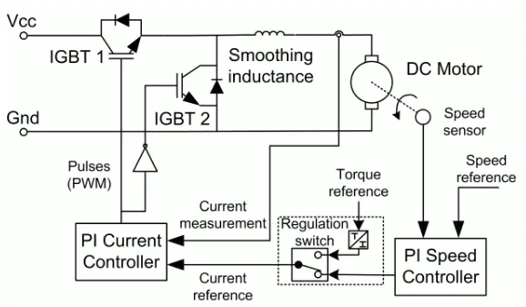
The Four-Quadrant Chopper DC Drive (DC7) block represents a four-quadrant, DC-supplied, chopper (or DC-DC PWM converter) drive for DC motors. This drive features closed-loop speed control with four-quadrant operation. The speed control loop outputs the reference armature current of the machine. Using a PI current controller, the chopper duty cycle corresponding to the commanded armature current is derived. This duty cycle is then compared with a sawtooth carrier signal to obtain the required PWM signals for the chopper.
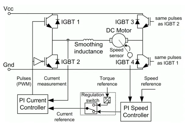
The Four-Quadrant Chopper DC Drive block uses these blocks from the Electric Drives/Fundamental Drive Blocks library:
-
Speed Controller (DC)
-
Regulation Switch
-
Current Controller (DC)
-
Chopper
The main advantage of this drive, compared with other DC drives, is that it can operate in all four quadrants (forward motoring, reverse regeneration, reverse motoring, and forward regeneration). In addition, due to the use of high switching frequency DC-DC converters, a lower armature current ripple (compared with thyristor-based DC drives) is obtained. However, four switching devices are required, which increases the complexity of the drive system.
Basic H Bridge
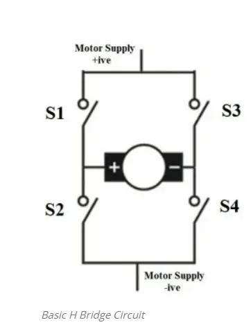
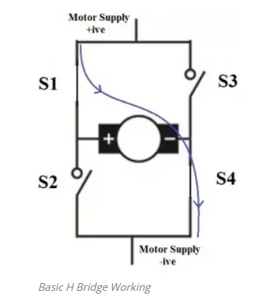
When switches S1 and S4 are switched on, motor runs in clockwise direction.
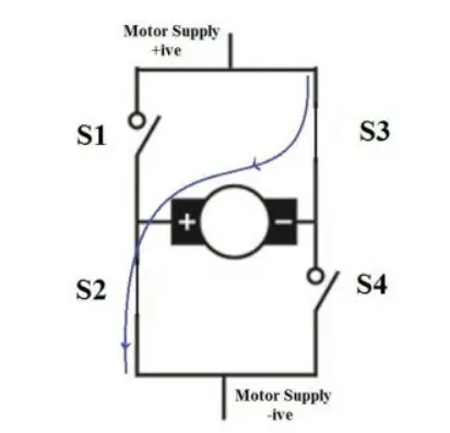
When S2 and S3 are switched on, motor runs in anticlockwise direction.
Transistorized H Bridge
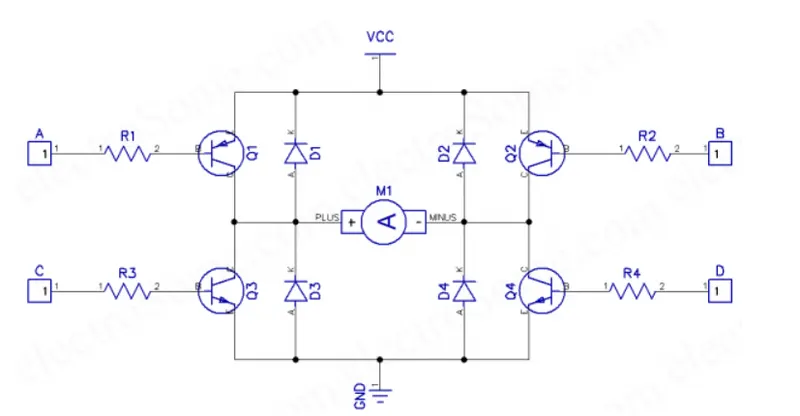
In this circuit all transistors are wired as switches. An NPN transistor (Q3 and Q4) will be ON when we give HIGH to it and a PNP transistor (Q1 and Q2) will be ON when we give LOW to it. So when (A = LOW, B = HIGH, C = LOW, D = HIGH), transistors Q1 & Q4 will be ON and Q2 & Q3 will be OFF, so the motor rotates in clockwise direction. Similarly when (A = HIGH, B = LOW, C = HIGH, D = LOW), transistors Q2 & Q3 will be ON and transistor Q1 & Q4 will be OFF, thus the motor rotates in anticlockwise direction. 1N4148 (D1 ~ D4) is uses as freewheeling diode as it is a fast switching diode. It avoids problems due to negative voltage produced by the back emf the dc motor. Resistors R1 – R4 are used to limit the input current of transistors and are designed in such a way that transistor will work as a switch. Transistor should be chosen according to the current requirements of the DC Motor.
Design of Input Resistors
- IL = Max. Motor Current
- Ib = IL/β, Minimum input current required to flow current IL through the load (active region).
- Ib’ = 10xIb, To make sure that transistor works in saturation region.
- Rin = (Vin – Vbe)/Ib’
- Take Vbe = 0.7V
This circuit is also used in inverters for producing alternate current across the load. In Square wave inverters, square wave is applied to inputs A, B and in sine wave inverters Pulse Width Modulated (PWM) square wave is applied to inputs A, B. Freewheeling diodes D1 – D4 can be avoided for resistive loads.
Main diffrence between both is that :-
1.H bridge is used to supply power to a two terminal device. By proper arrangement of the switches, the polarity of the power to the device can be changed. Two example discussed below, DC motor Driver and transformer of switching regulator. Note that, not all of the case of switching condition is safe. The "short"(see below in "DC motor driver" section) cases are dangerous to the power source and to the switches.
2. Four-Quadrant Chopper DC Drive:- Speed Torque & Power Relationship - Circuit Globe Four Quadrant Operation of any drives or DC Motor means that the machine operates in four quadrants. They are Forward Braking, Forward motoring, Reverse motoring and Reverse braking.
2. Develop a 2-quadrant chopper using simulink & explain the working of the same with the relevant results. (Refer to article - Multiquadrant operation of motor )
introduction :
Chopper circuits are known as DC to DC converters. Similar to the transformers of the AC circuit, choppers are used to step up and step down the DC power. They change the fixed DC power to variable DC power. Using these, DC power supplied to the devices can be adjusted to the required amount.
Principle of Operation
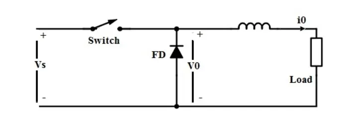
The principle of operation of chopper can be understood from the circuit diagram below. The circuit consists of a semiconductor diode, resistor, and a load. For all type of chopper circuit, the output voltage value is controlled by periodic closing and opening of the switches used in the circuit.
The chopper can be viewed as an ON/OFF switch that can rapidly connect or disconnect the source to load connection. Continuous DC is given as source to the chopper as Vs and chopped DC is obtained across the load as V0.
Output Voltage and Current Waveforms
Above are the output voltage and current waveforms of a chopper circuit. From the voltage waveform, it can be seen that during the period of TON the load voltage V0 is equal to the source voltage Vs. But when the interval TOFF occurs, the DC voltage step downs to zero, thus making the load short-circuited.
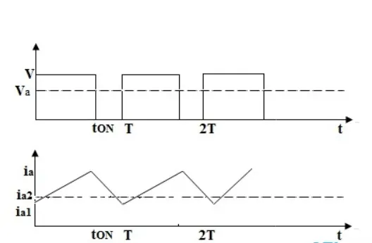
In the current waveform, it can be seen that during the interval TON the load current rises to the maximum value. During the interval TOFF, the load current decays. In TOFF condition the chopper is off so, the load voltage becomes zero. But load current flows through the diode FD, making the load short-circuited.
Thus, the chopped DC voltage is produced at the load. The current waveform is continuous which rises during TON state and decays during TOFF state.
Applications of Chopper
DC to DC converters are applied for many applications such as in
- Switched Mode Power Supply System.
- in DC motors as speed controllers.
- DC voltage boosters.
- Battery chargers.
- Railway systems.
- Electric cars etc…
Choppers are used in signal processing systems also. In choppers, the output voltage can be controlled using many different techniques such as Pulse width modulation, Frequency modulation, Variable frequency, variable pulse width, CLC control, etc.
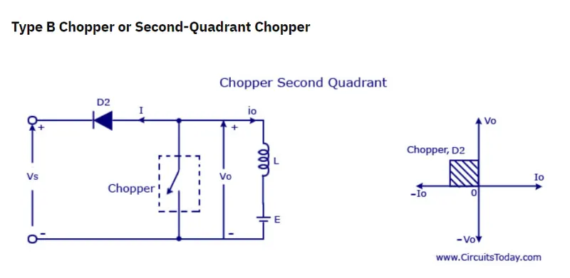
In type B or second quadrant chopper the load must always contain a dc source E . When the chopper is on, v0 is zero but the load voltage E drives the current through the inductor L and the chopper, L stores the energy during the time Ton of the chopper . When the chopper is off , v0 =( E+ L . di/dt ) will be more than the source voltage Vs . Because of this the diode D2 will be forward biased and begins conducting and hence the power starts flowing to the source. No matter the chopper is on or off the current I0 will be flowing out of the load and is treated negative . Since VO is positive and the current I0 is negative , the direction of power flow will be from load to source. The load voltage V0 = (E+L .di/dt ) will be more than the voltage Vs so the type B chopper is also known as a step up chopper .
The Two-Quadrant Chopper block represents a two-quadrant controlled chopper for converting a fixed DC input to a variable DC output. The block contains two switching devices. Options for the type of switching devices are:
-
GTO — Gate turn-off thyristor. For information about the I-V characteristic of the device, see GTO.
-
Ideal semiconductor switch — For information about the I-V characteristic of the device, see Ideal Semiconductor Switch.
-
IGBT — Insulated-gate bipolar transistor. For information about the I-V characteristic of the device, see IGBT (Ideal, Switching).
-
MOSFET — N-channel metal-oxide-semiconductor field-effect transistor. For information about the I-V characteristic of the device, see MOSFET (Ideal, Switching).
-
Thyristor — For information about the I-V characteristic of the device, see Thyristor (Piecewise Linear).
-
Averaged Switch — Semiconductor switch with an anti-parallel diode. The control signal port, G, accepts values in the
[0,1]interval. When the value at port G is equal to0or1, the averaged switch is either fully opened or fully closed, and it behaves similarly to the Ideal Semiconductor Switch block with an anti-parallel diode. When the value at port G is between0and1, the averaged switch is partly opened. You can then average the PWM signal over a specified period. This allows for undersampling of the model or using modulation waveforms instead of PWM signals.
Specify Chopper Quadrants
You can choose the quadrants where the Two-Quadrant Chopper operates. To select the quadrants, set the Modeling option parameter to either:
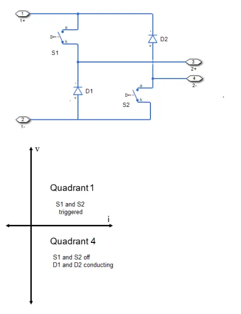
The Two-Quadrant Chopper DC Drive block uses these blocks from the Electric Drives/Fundamental Drive Blocks library:
-
Speed Controller (DC)
-
Regulation Switch
-
Chopper
3. Explain in a brief about operation of BLDC motor.
Introduction:
BLDC Motor Definition: BLDC Motor also known as Brushless DC Motor is a motor-operated without brushes to overcome certain difficulties. The basic difference between a brushed one and BLDC is operating with and without brushes. A normal machine operates with brushes used to either collect or send current to the commutator.
The Brushless DC Motor
The brushless DC (BLDC) motor is really an AC motor! The current through it alternates,as we will see. It is called a ‘brushless DC motor’ because the alternating current mustbe variable frequency and so derived from a DC supply, and because its speed/torquecharacteristics are very similar to the ordinary ‘with brushes’ DC motor. As a result of
‘BLDC’ being not an entirely satisfactory name, it is also known as a ‘self-synchronous.
AC motor’, a ‘variable frequency synchronous motor’, a ‘permanent magnet synchronousmotor’ and an ‘electronically commutated motor’ (ECM).
operation:
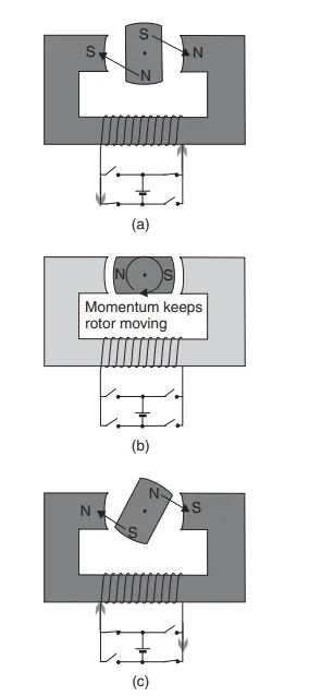
The basis of operation of the BLDC motor is shown in Figure 7.24. The rotor consistsof a permanent magnet. In Figure 7.24a the current flows in the direction that magnetises the stator so that the rotor is turned clockwise, as shown. In Figure 7.24b the rotor passes between the poles of the stator, and the stator current is switched off. Momentum
carries the rotor on, and in Figure 7.24c the stator coil is re-energised, but the currentand hence the magnetic field are reversed. So the rotor is pulled on round in a clockwise direction. The process continues, with the current in the stator coil alternating.
Obviously, the switching of the current must be synchronised with the position of the rotor. This is done using sensors. These are often Hall effect sensors that use the magnetism of the rotor to sense its position, but optical sensors are also used.
These BLDC motors need a strong permanent magnet for the rotor. The advantage of this is that currents do not need to be induced in the rotor (as with, for example, the induction motor), making them somewhat more efficient and giving a slightly greater specific power.
Permanent magnet synchronous motors which are a type of BLDC motors are increasingly used in electric vehicles. Modern electronics allow the supply frequency to be continuously varied so that it can be used to control the motor speed and hence the vehicle speed. Permanent magnet synchronous motors are highly efficient and tend to replace induction motors in many applications. This is due to the fact that permanent magnet motors have a higher torque-to-volume ratio as compared with the induction motors.
Also, the decrease in the manufacturing cost of permanent magnets makes the permanent
magnet motors appealing