Week-7 Challenge: DC Motor Control
Aim:
A. Explain a MATLAB demo model named ‘Speed control of a DC motor using BJT H-bridge’.
B. Comment on the armature current shoot-up from the scope results.
C. Refer to the help section of ‘The Four-Quadrant Chopper DC Drive (DC7) block’. Compare it with the H-bridge model.
2. Develop a 2-quadrant chopper using Simulink & explain the working of the same with the relevant results. (Refer to the article - Multiquadrant operation of the motor )
3. Explain in a brief the operation of BLDC motor.
Explain a MATLAB demo model named ‘Speed control of a DC motor using BJT H-bridge’.
The Bipolar Junction Transistor (BJT) when used for power switching applications, operates as an IGBT. When it is conducting (BJT operating in the saturated region), a forward voltage Vf is developed between collector and emitter (in the range of 1 V). Therefore, the IGBT block can be used to model the BJT device.
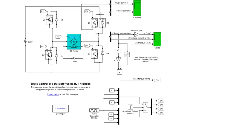
The IGBT block does not simulate the gate current controlling the BJT or IGBT. The switch is controlled by a Simulink® signal (1/0). The DC motor uses the preset model (5 HP 24V 1750 rpm). It simulates a fan type load (where Load torque is proportional to the square of speed). The armature means voltage can be varied from 0 to 240 V when the duty cycle (specified in the Pulse Generator block) is varied from 0 to 100%.
The motor starts in the positive direction with a duty cycle of 75% (mean DC voltage of 180V). At t= 0.5 sec., the armature voltage is suddenly reversed and the motor runs in the negative direction.
Explanation:
As above mentioned the model uses the IGBT switch for changing the voltage positively and negatively simultaneously.
the voltage source battery supplying the 240V. the duty cycle is taken as 75%.
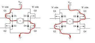
The four numbers of the diode are connected to the four Igbt switches in the H bridge configuration. two transistors are switched simultaneously: Q1 and Q4 or Q2 and Q3. When Q1 and Q4 are fired, a positive voltage is applied to the motor, and diodes D2-D3 operate as free-wheeling diodes when Q1 and Q4 are switched off. When Q2 and Q3 are fired, a negative voltage is applied to the motor, and diodes D1-D4 operate as free-wheeling diodes when Q2 and Q3 are switched off.
The DC motor taken in the model is a wound field Dc machine, the field connection provided so that machine can be used as a separately excited.
The speed of the motor is shown in the scope in RPm which is converted from rad/sec with the use of an element-wise gainer.
the torque is calculated by applying the formula:
T = k*w^2.
Now, the signals are generated by using the pulse generator having a frequency of 500hz. the step block is used to provide the steps of armature voltage control.
The switch block is used to provide the signals to the IGBT according to the pulse generator, the P1,P2,P3,P4 goto block send the signals to the IGBT switch when they they get the pulses which is controlled by the threshold switch
Comment on the armature's current shoot-up from the scope results.
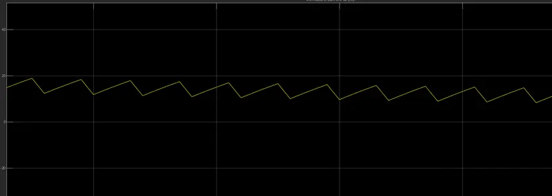
The armature current follows the triangular paths which show the continuous sine wave.
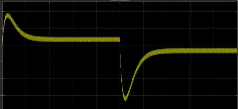
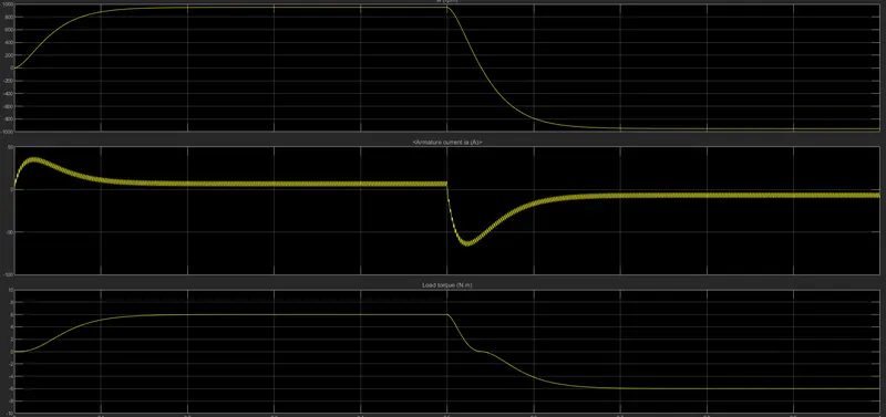
at the initial phase, the current climbed up to a certain level near the 50A as the initial torque is high and then drops from the cliff and becomes constant between 5-4 A. when the torque becomes steady.
while the torque becomes negative which shows the reverse motoring condition the armature current also becomes negative which shows the change of direction in the flow of current.
Conclusion:
- in forwarding motoring the flow of current is positive to negative while in the case of reverse motoring it changed from negative to positive.
- the armature current is rise with the rise in torque and as the torque becomes steady the current also becomes steady.
- the triangle paths show the current follows the sine wave.
Refer to the help section of ‘The Four-Quadrant Chopper DC Drive (DC7) block’. Compare it with the H-bridge model.
Description
The 200 HP DC motor is separately excited with a constant 150 V DC field voltage source. The armature voltage is provided by an IGBT converter controlled by two PI regulators. The converter is fed by a 515 V DC bus obtained by rectification of a 380 V AC 50 Hz voltage source. In order to limit the DC bus voltage during dynamic braking mode, a braking chopper has been added between the diode rectifier and the DC7 block.
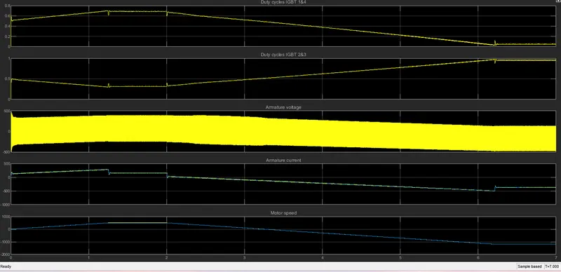
The first regulator is a speed regulator, followed by a current regulator. The speed regulator outputs the armature current reference (in p.u.) used by the current controller in order to obtain the electromagnetic torque needed to reach the desired speed. The speed reference change rate follows acceleration and deceleration ramps in order to avoid sudden reference changes that could cause armature over-current and destabilize the system. The current regulator controls the armature current by computing the appropriate duty ratios of the 5 kHz pulses of the four IGBT devices (Pulse Width Modulation). For proper system behavior, the instantaneous pulse values of IGBT devices 1 and 4 are opposite to those of IGBT devices 2 and 3. This generates the average armature voltage needed to obtain the desired armature current. In order to limit the amplitude of the current oscillations, a smoothing inductance is placed in series with the armature circuit.
Comparison :
- The H bridge circuit generally works in the 2 quadrants while the Four quadrant chopper works in the four-quadrant
- the supply in the H bridge is DC and the supply in the 4 quadrant chopper is 3 phase 3820V 50hz Ac supply which is further converted into Dc by the AC to DC converter.
- The H bridge configuration has the IGBT switches and the diodes but in the four quad. chopper block has the DC machine, converter, and the controller
- In the Four quad chopper, two separate duty cycle is built. one is for IGBT1&4 another one for the 2&3
Scope of the Four quadrant DC chopper:
Develop a 2-quadrant chopper using Simulink & explain the working of the same with the relevant results. (Refer to the article - Multiquadrant operation of the motor )
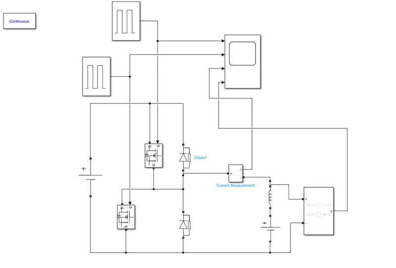
Sometimes a chopper may be required to provide a two-quadrant operation by retaining the current direction in both motoring and braking modes. Such a Two Quadrant Chopper and its waveforms The chopper permits a change in the polarity of terminal voltage keeping the direction of current constant. In Fig. S1 and S2 are the choppers working as electronic switches and D1 and D2 are the feedback diodes. Assuming continuous conduction, both S1 and S2 operate simultaneously.
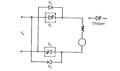
When they are ON, the load current Id increases, with the rate of rising depending upon the back emf and torque of the machine. When they are OFF, the load current is fed to the supply through the diodes D1 and D2. The current decreases in this stage. it is clear that the load voltage is effectively negative when the diodes conduct.
Model description:
- The Pulse generator is used to provide the pulses to the MOSFET switches, the two separate pulse generator is used to provide the pulse simultaneously to both the switches.
- The MOSFET switches provide the voltage when it's in the ON state, when it is in the OFF state the current flows across the two diodes. The MOSFET fetches the signals from the pulse generator via, Gate
- the inductance is connected with the Battery source which stimulates the current flows when both the switches are in the off condition.
- the scope is attached with the current and voltage measurement blocks. which calculates the current and voltage across the circuit.
- The powergui block is placed which is continuous to set the simulation type, parameters, and the preferences to measure the current and voltage.
Result:
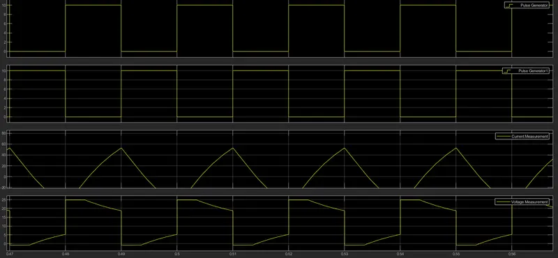
- The current goes to the negative between the change of the pulses.
- the current is at the peak while the pulses are changed one from 0-10 and the other from 10-0.
- the voltage remains positive throughout the cycle.
- the voltage drops when the current goes to its peak point due to the inductance.
Explain in a brief the operation of the BLDC motor.
A motor converts supplied electrical energy into mechanical energy. Various types of motors are in common use. Among these, brushless DC motors (BLDC) feature high efficiency and excellent controllability and are widely used in many applications. The BLDC motor has power-saving advantages relative to other motor types.
The simplest type of motor is the brushed DC motor. In this type of motor, electrical current is passed through coils that are arranged within a fixed magnetic field. The current generates magnetic fields in the coils; this causes the coil assembly to rotate, as each coil is pushed away from the like pole and pulled toward the unlike pole of the fixed field. To maintain rotation, it is necessary to continually reverse the current—so that coil polarities will continually flip, causing the coils to continue “chasing” the, unlike fixed poles. Power to the coils is supplied through fixed conductive brushes that make contact with a rotating commutator; it is the rotation of the commutator that causes the reversal of the current through the coils. The commutator and brushes are the key components distinguishing the brushed DC motor from other motor types.
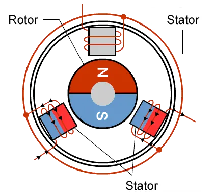
As their name implies, brushless DC motors do not use brushes. With brushed motors, the brushes deliver current through the commutator into the coils on the rotor. So how does a brushless motor pass current to the rotor coils? It doesn’t—because the coils are not located on the rotor. Instead, the rotor is a permanent magnet; the coils do not rotate, but are instead fixed in place on the stator. Because the coils do not move, there is no need for brushes and a commutator.
With the brushed motor, rotation is achieved by controlling the magnetic fields generated by the coils on the rotor, while the magnetic field generated by the stationary magnets remains fixed. To change the rotation speed, you change the voltage for the coils. With a BLDC motor, it is the permanent magnet that rotates; rotation is achieved by changing the direction of the magnetic fields generated by the surrounding stationary coils. To control the rotation, you adjust the magnitude and direction of the current into these coils.