Week-7 Challenge: DC Motor Control
CASE 1
A] Speed control of a DC motor using BJT H-bridge :-
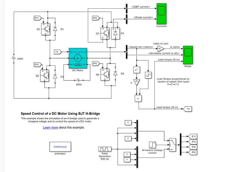
The Bipolar Junction Transistor (BJT) when used for power switching applications, operates as an IGBT. When it is conducting (BJT operating in the saturated region), a forward voltage Vf is developed between collector and emitter (in the range of 1 V). Therefore, the IGBT block can be used to model the BJT device.
The IGBT block does not simulate the gate current controlling the BJT or IGBT. The switch is controlled by a Simulink® signal (1/0). The DC motor uses the preset model (5 HP 24V 1750 rpm). It simulates a fan type load (where Load torque is proportional to square of speed). The armature mean voltage can be varied from 0 to 240 V when the duty cycle (specified in the Pulse Generator block) is varied from 0 to 100%.
The H-bridge consists of four BJT/Diode pairs (BJT simulated by IGBT models). Two transistors are switched simultaneously: Q1 and Q4 or Q2 and Q3. When Q1 and Q4 are fired, a positive voltage is applied to the motor and diodes D2-D3 operate as free-wheeling diodes when Q1 and Q4 are switched off. When Q2 and Q3 are fired, a negative voltage is applied to the motor and diodes D1-D4 operate as free-wheeling diodes when Q2 and Q3 are switched off.
Simulation
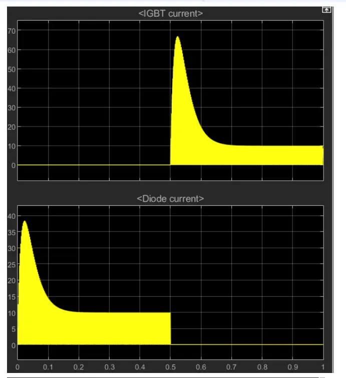
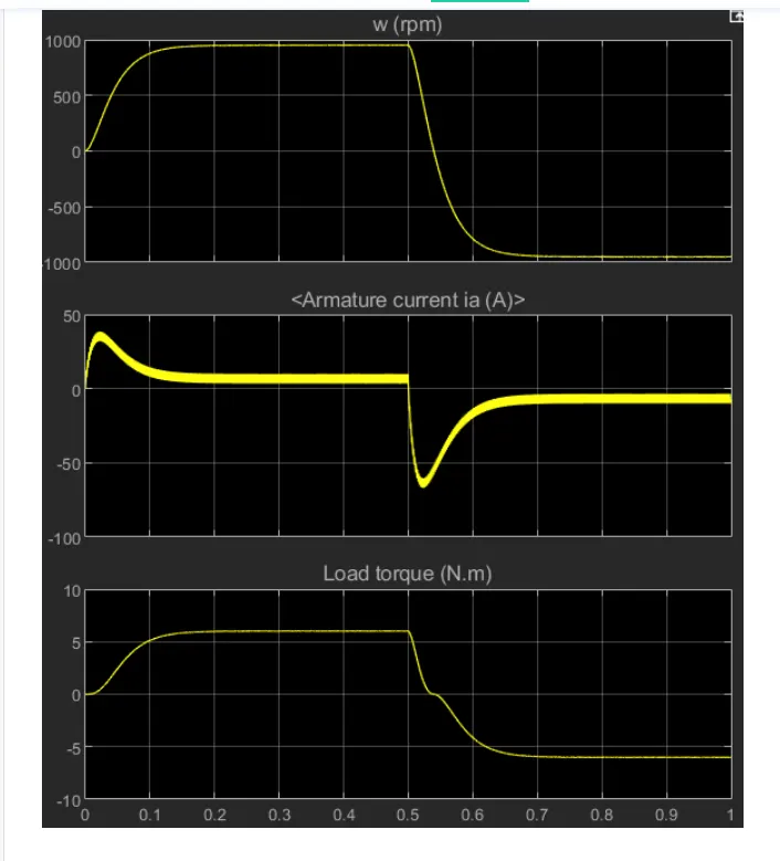
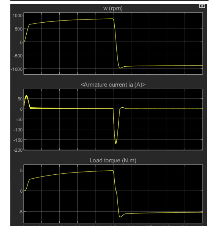
The motor starts in the positive direction with a duty cycle of 75% (mean DC voltage of 180V). At t= 0.5 sec., the armature voltage is suddenly reversed and the motor runs in the negative direction.
'Scope' shows motor speed, armature current and load torque and 'Currents' shows currents flowing in BJT Q3 and diode D3.
B] Speed control of a DC motor using BJT H - bridge -
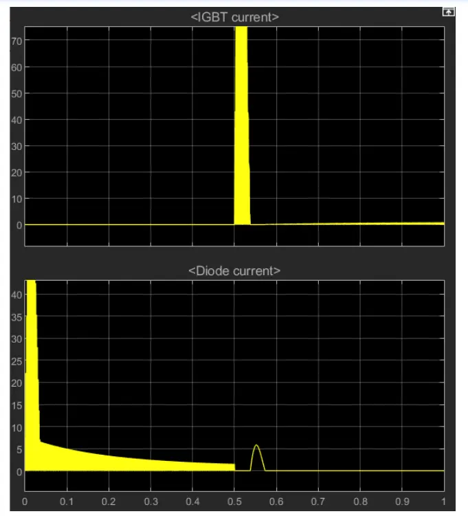
5HP 240V 1750RPM
Field Voltage = 150
Torque TL Mechanical input
C] The Four-Quadrant Chopper DC Drive (DC7) block’. Compare it with the H-bridge model.
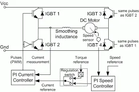
The Four - Quadrant Chopper DC Drive ( DC7 ) block represents a four - quadrant , DC - supplied , chopper drive for DC motors . This drive features closed - loop speed control with the four - quadrant operation .
The main advantage of this drive , compared with other DC drives , is that it can operate in all four quadrants ( forward motoring , reverse regeneration , reverse motoring , and forward regeneration ) . In addition , due to the use of high switching frequency DC - DC converters , a lower armature current ripple ( compared with thyristor - based DC drives ) is obtained . However , four switching devices are required , which increases the complexity of the drive system .
The Four - Quadrant Chopper DC Drive block uses these blocks from the Electric Drives
• Speed Controller ( DC )
• Regulation Switch
• Current Controller ( DC )
• Chopper
H - bridge model
The H - Bridge block represents an H - bridge motor driver . The block has the following two Simulation mode options :
PWM - The H - Bridge block output is a controlled voltage that depends on the input signal at the PWM port . If the input signal has a value greater than the Enable threshold voltage parameter value , the H - Bridge block output is on and has a value equal to the value of the Output voltage amplitude parameter . If it has a value less than the Enable threshold voltage parameter value , the block maintains the load circuit using one of the following three Freewheeling mode options :
- One semiconductor switch and one freewheeling diode
- Two freewheeling diodes .
- Two semiconductor switches and one freewheeling diode.
Averaged This mode has two Load current characteristics options :
- Smoothed .
- Unsmoothed or discontinuous
Comparison
S.No Four - Quadrant Chopper DC Drive ( DC7 ) block H - bridge model
1 .Generally used in Automotive for controlling DC motor speed and direction . Used in Robotics & Electromech Device.
2. Regenerative braking is possible in DC7. Dynamic braking is only possible.
3 . It can operate in all 4 quadrants of DC motors . It can only operate only in forward and reverse directions .
4 . Only DC - DC converters high switching frequency is possible . It shows the simulation value in accurate mode .
5. It has a wider range of torque and output power . It has a narrow torque an output power.
CASE 2
2-quadrant chopper .
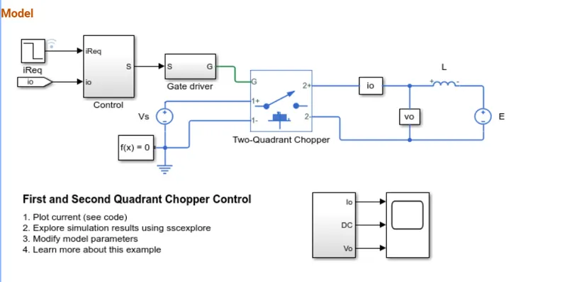
This example shows how to control a two-quadrant chopper. The two-quadrant chopper operates in the first and second quadrants, allowing positive and negative output current. The Control subsystem implements a simple PI-based control algorithm for controlling the output current. The load of the system is considered constant throughout the simulation.
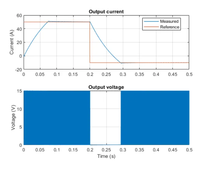
The plot below shows the requested and measured current for the test and the output voltage in the circuit.
CASE 3
BLDC Motor
A brushless DC motor (also known as a BLDC motor or BL motor) is an electronically commuted DC motorwhich does not have brushes. The controller provides pulses of current to the motor windings which control the speed and torque of the sync motor.
These types of motors are highly efficient in producing a large amount of torque over a vast speed range. In brushless motors, permanent magnets rotate around a fixed armature and overcome the problem of connecting current to the armature. Commutation with electronics has a large scope of capabilities and flexibility. They are known for smooth operation and holding torque when stationary.
How the BLDC motor Work;
Before explaining the working of a brushless DC motor, it is better to understand the function of a brushed motor. In brushes motors, there are permanent magnets on the outside and a spinning armature which contains electromagnet is inside. These electromagnets create a mag. field in the armature when the power is switched on and help to rotate the armature.
The brushes change the polarity of the pole to keep the rotation on of the armature. The basic working principle for the brushed DC motor and for brushless DC motor are same i.e. internal shaft position feedback.
Brushless DC motor has only two basic parts: rotor and the stator. The rotor is the rotating part and has rotor magnets whereas stator is the stationary part and contains stator windings. In BLDC permanent magnets are attached in the rotor and move the electromagnets to the stator. The high power transistors are used to activate electromagnets for the shaft turns. The controller performs power distribution by using a solid-state circuit.
Types of BLDC Motor;
Basically, BLDC are of two types, one is outer rotor motor and other is inner rotor motor. The basic difference between the two is only in designing, their working principles are same.
Inner Rotor Design :
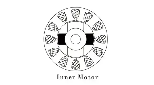
In an inner rotor design, the rotor is located in the centre of the motor and the stator winding surround the rotor. As the rotor is located in the core, rotor magnets do not insulate heat inside and heat get dissipated easily. Due to this reason, inner rotor designed motor produces a large amount of torque and validly used.
Outer Rotor Design :
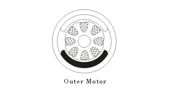
In outer rotor design, the rotor surrounds the winding which is located in the core of the motor. The magnets in the rotor trap the heat of the motor inside and do not allow to dissipate from the motor. Such type of designed motor operates at lower rated current and has low cogging torque.
The advantages of a BLDC motor are:
- Brushless motors are more efficient as its velocity is determined by the frequency at which current is supplied, not the vltg.
- As brushes are absent, the mechanical energy loss due to friction is less which enhanced efficiency.
- BLDC motor can operate at high-speed under any condition.
- There is no sparking and much less noise during operation.
- More electromagnets could be used on the stator for more precise control.
- BLDC motors accelerate and decelerate easily as they are having low rotor inertia.
- It is high performance motor that provides large torque per cubic inch over a vast sped rang.
- BLDC motors do not have brushes which make it more reliable, high life expectancies, and maintenance free operation.
- There is no ionizing sparks from the commutator, and electromagnetic interference is also get reduced.
- Such motors cooled by conduction and no air flow are required for inside cooling.
The disadvantages of a BLDC motor are:
- BLDC motor cost more than a brushed DC motor.
- The limited high power could be supplied to BLDC motor, otherwise, too much heat weakens the magnets and the insulation of winding may get damaged.