Project-1: Powertrain for aircraft in runways
CASE-1
Search and list out the total weight of various types of aircrafts.
The aircraft gross weight ( also known as the all - up weight and abbreviated AUW ) is the total aircraft weight at any moment during the flight or ground operation.
An aircraft's gross weight will decrease during a flight due to fuel and oil consumption . An aircraft's gross weight may also vary during a flight due to payload dropping or in - flight refuelling .
At the moment of releasing its brakes , the gross weight of an aircraft is equal to its takeoff weight . During flight , an aircraft's gross weight is referred to as the en - route weight or in - flight weight.
The following image depicts takeoff weight components.
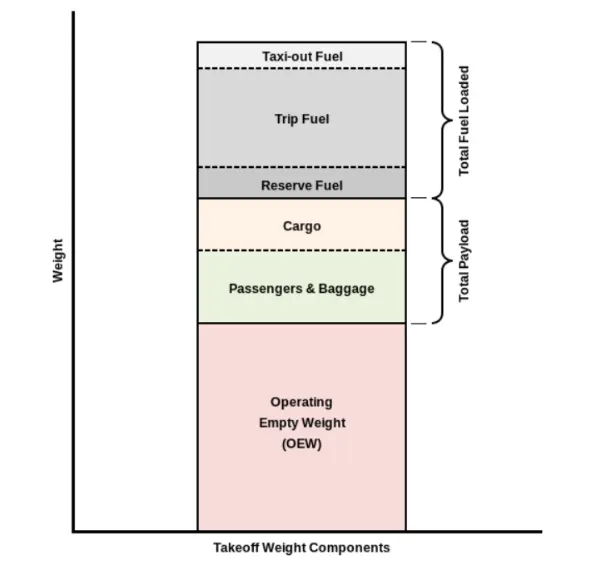
A brief description about these is below:
Airbus A380-800 575,000 394
Boeing 747-8F 447,700 346.091
Boeing 747-8 443,613 306.175
Boeing 747-400ER 412,770 295.742
MANUFACTURER EMPTY WEIGHT (MEW):-Also called Manufacturer's Weight Empty (MWE) or Licensed Empty Weight.
It is the weight of the aircraft "as built" and includes the weight of the structure, power plant, furnishings, installations,
systems and other equipment that are considered an integral part of an aircraft.
This excludes any baggage, passengers, or usable fuel .
ZERO FUEL WEIGHT (ZFW):-
This is the total weight of the airplane and all its contents (including unusable fuel), but excluding the total weight of the
usable fuel on board.
As a flight progresses and fuel is consumed, the total weight of the airplane reduces, but the ZFW remains constant.
Maximum zero fuel weight (MZFW) is the maximum weight allowed before usable fuel and other specified usable agents
(engine injection fluid, and other consumable propulsion agents) are loaded.
OPERATING EMPTY WEIGHT (OEW):-(Roughly equivalent to basic empty weight on light aircraft)
It is the basic weight of an aircraft including the crew, all fluids necessary for operation such as engine oil, engine
coolant, water, unusable fuel and all operator items and equipment required for flight but excluding usable fuel and the
payload.
It is the carrying capacity of an aircraft. It includes cargo, people, extra fuel. In the case of a commercial airliner, it may
refer only to revenue-generating cargo or paying passengers.
MAXIMUM TAKE-OFF WEIGHT (MTOW):-
This is the maximum weight at which the pilot of the aircraft is allowed to attempt to take off .
REGULATED TAKE OF WEIGHT (RTOW):-
pending on different factors (e.g. flap setting, altitude, air temperature, length of runway), RTOW or maximum
permissible takeoff weight varies for each takeoff. It can never be higher than MTOW.
MAXIMUM LANDING WEIGHT (MLW):-
This maximum weight at which an aircraft is permitted to land.
CASE-2
Is there any difference between ground speed and air speed?
There is a difference between ground speed and air speed to understand this we should take into account wind speed too.
Wind Speed
For a reference point picked on the ground the air moves relative to the referance point at the wind speed Notice that the wind speed is a vector quantity and has both a magnitude and a direction Direction is important . A 20 mph wind from the west is different from a 20 mph wind from the east . The wind has components in of three primary directions ( north - south , east - west , and up - down ) in this figure , we are considering only velocities along the aircrafts Fight poth A positive velocity is defined to be in the direction of the aircraft's motion we are neglecting cross winds , which occur perpendicular to the fight path but parallel to the ground , and updrafts and downdrafts , which occur perpendicular to the ground.
Ground Speed
For a reference point picked on the ground , the aircraft moves relative to the reference point of the ground speed Ground speed is also a vector quantity so a comparison of the ground speed to the wind speed must be done . according to rules for vector comparisons.
Airspeed
The important quantity in the generation of lift is the relative velocity between the object and the air , which is called the airspeed Airspeed cannot be directly measured from a ground position , but must be computed from the ground speed and the wind speed . Airspeed is the vector difference between the ground speed and the wind speed.
Airspeed=Ground Speed - Wind Speed
On a perfectly stit day , the airspeed is equal to the ground speed But if the wind is blowing in the same direction that the aircraft is moving the airspeed will be less than the ground speed.
For example taking wind speed as 20 km / hr and runway is east - west runway the wind blowing towards west and the flight runs at 80 km / nr the wind speed acting in the west and the fight takes off east then the,
Airspeed=Groundspeed ( 80 ) - Wind Speed ( -20 ) -100 km / hr
if the planes runs towards west along the wind blowing direction then the,
Airspeed =Groundspeed ( 80 ) - wind Speed ( 20 ) -80km / hr
Hence there is a difference between ground speed and air speed.
CASE-3
Why is it not recommended to use aircraft engine power to move it on the ground at Airport?
The following are some limitations why we can't use the full Engine power on ground
i. The area infront of the jet engine creates a space where any equipment or people can be sucked into the engine
anything is too close.
ii. Applying the gas can create a blast behind the engines.
iii. Areas infront of the engines are critical factors when applying the power to them, so we can't ignore them easily.
iv. People, Things can be damaged if they are tear to the plane from the jet blast.
v. Air intake is very powerful that it can even suck the human bodies.
vi. Due to high suction it may intake the small dust particles, stones, papers etc which may damage the engines.
vii. The noise obtained from the plane is more and also fumes gave more heat.
So it is not recommendable to move the aircraft on ground with Engine power which has dangerous affects.
CASE-4
How an aircraft is pushed to runway when its ready to take off?
In aviation , pushback is an airport procedure during which an aircraftis pushed backwards away from an airport gate by external power . Pushbacks are carried out by special , low - profile vehicles called pushback tractors or tugs.
Although many aircraft are capable of moving themselves backwards on the ground using reverese thrust ( a procedure referred to as a powerback ) , the resulting jetblast or propwash might cause damage to the terminal building or equipment . Engines close to the ground may also blow sand and debris forward and then suck them into the engine , causing damage to the engine . A pushback is therefore the preferred method to move the aircraft away from the gate .
Pushbacks at busy aerodromes are usually subject to ground control clearance to facilitate ground movement on taxiways . Once clearance is obtained , the pilot will communicate with the tractor driver ( or a ground handler walking alongside the aircraft in some cases ) to start the pushback . To communicate , a headset may be connected near the nose gear .
Since the pilots cannot see what is behind the aircraft , steering is done by the pushback tractor driver and not by the pilots . Depending on the aircraft type and airline procedure , a bypass pin may be temporarily installed into the nose gear to disconnect it from the aircraft's normal steering mechanism .
Once the pushback is completed , the towbar is disconnected , and any bypass pin removed . The ground handler will show the bypass pin to the pilots to make it clear that it has been removed . The pushback is then complete , and the aircraft can taxi forward under its own power .
CASE-5
Learn about take off power, tyre design, rolling resistance, tyre pressure, brake forces when landing.
Take-off -
Is the phase of flight in which an aerospace vehicle leaves the ground and becomes airborne. For light aircraft,
usually fullpower is used during take-off. Large transport category (airliner) aircraft may use a reduced power for takeoff, where less than fullpower is applied in order to prolong engine life, reduce maintenance costs and reduce noise
emissions. In some emergency cases,the power used can then be increased to increase the aircraft's performance. The
aircraft is permitted to accelerate to rotation speed often referred to as V . The term rotation is used because the aircraft
pivots around the axis of its mainlanding gear while still on theground, usually because of gentle manipulation of the
flight controls to make or facilitate this change in aircraft altitude.Fixed-wing aircraft designed for high-speed operation
such as commercial jet aircraft have difficulty generating enough lift at thelow speeds encountered during takeoff.
These are therefore fitted with high lift devices, often including slats and usually flaps, whichincrease the camber and
often area of the wing, making it more effective at low speed, thus creating more lift. These are deployedfrom the wing
before takeoff, and retracted during the climb. They can also be deployed at other times, such as before landing.The
speeds needed for take-off are relative to the motion of the air (indicated airspeed). A headwind will reduce the ground
speedneeded for take-off, as there is a greater flow of air over thewings. Typical take-off air speeds for jetliners are in
the range of 240–285km/h ,130–154 kn; 149–177 mph.
Tyre Design-
Based on the type of piles used the tyres can be,
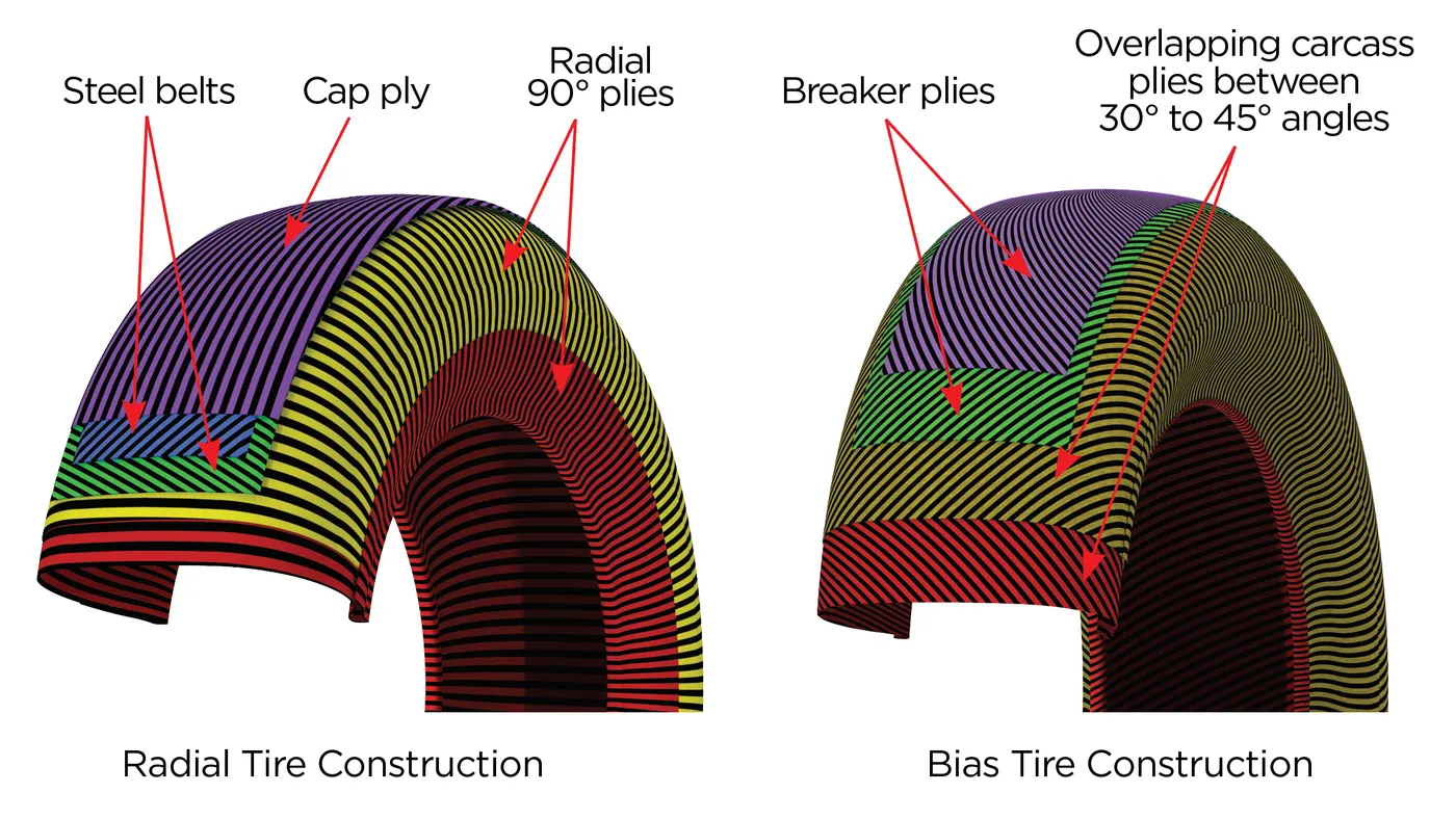
Radial ply tires:-
These tyres feature a tenibile casing which is constructed of rubber - coated ply cords which extend around the beads and are substantially at 90 to the centerline of the tread the cosing is atobilled by an essery bestensible circumferential belt.
Blas ply tires:-
These tyres feature a casing which is constructed of alternate layers of rubber - coated ply cords which extend around the beads and are at alternate angles substantially less than 90 to the center line of the tread.
Based on the method for containing the inflation gas the tyres can be ,
- Tube type tyres- These require tubes for inflation retention .
- Tubeless tyres- These do not require tubes . They are constructed with an innerliner ( integral rubber lining that is engineered to prevent the diffusion of the inflation gas into the casing )
Rolling Resistance-
The force that resists the motion of a body rolling on a surface is called the rolling resistance or the rolling friction. The
friction
between aircraft and runway will be proportional to the normal force exerted by the aircraft on the runway.
F=μ(W−L)
The normal force will be the difference between Weight of aircraft and Lift, the friction coefficient will be typically of a
magnitude of 0.02 for a standard tarmac runway.
Tyre Pressure-
An aircraft tyre is designed to withstand extremely heavy loads for short durations. The number of tires required for
aircraft increases with the weight of the aircraft, as the weight of the airplane needs to be distributed more evenly.
Aircraft tire tread patterns are designed to facilitate stability in high crosswind conditions, to channel water away to
prevent hydroplaning, and for braking effect. Aircraft tires generally operate at high pressures, up to 200 psi (14 bar; 1,400
kPa) for airliners, and even higher for business jets. Tests of airliner aircraft tires have shown that they are able to sustain
pressures of maximum 800 psi (55 bar; 5,500 kPa) before bursting. During the tests the tires have to be filled with water,
to prevent the test room being blown apart by the energy that would be released by a gas when the tire bursts.
Aircraft tires are usually inflated with nitrogen to minimize expansion and contraction from extreme changes in ambient
temperature and pressure experienced during flight. Dry nitrogen expands at the same rate as other dry atmospheric
gases (normal air is about 80% nitrogen), but common compressed air sources may contain moisture, which increases
the expansion rate with temperature.
The requirement that an inert gas, such as nitrogen, be used instead of air for inflation of tires on certain transport
category airplanes was prompted by at least three cases in which the oxygen in air-filled tires combined with volatile
gases given off by a severely overheated tire and exploded upon reaching autoignition temperature. The use of an inert
gas for tire inflation will eliminate the possibility of a tire explosion.
Brake forces when landing-
Bringing an aircraft down to the runway from 37,000 feet is only part of the challenge. It’s not over until the aircraft is
safely parked atits gate.
A large amount of brake force is required to stop the aircraft after landing on the runway since the speed of the
aircraft is quite high in the range of 250-300 kmph. In order to calculate the brake force required to stop the aircraft, we
have to first estimate the kinetic energy carried by it and this can be determined by, Once the energy has been
calculated, and if we assume the minimum distance in which the vehicle has to be stopped we cancalculate the brake
force required and the same has to be applied on the wheels of the aircraft.
Stopping a 200-tonne aircraft landing at 180 mph 290 kmph requires a lot of braking force. The 787 has one brake unit
on each of the eight wheels on the main gear assembly. On other aircraft types, the brake units are powered by the
hydraulics system. An electrical signal is sent from the flight deck to hydraulic actuators near the main landing gear.
Here, hydraulic fluid at 3,000 pound per square inch 20.68 KN/m2 is used to force the brake unit against the wheel, thus
slowing it down. This system works fine, but the pipes and actuators that form this part of the hydraulic system come at
a considerable weight cost. Extra weight means more fuel burn, which in turn increases costs and carbon emissions.
Electrical brakes:
The brake system on the 787 Dreamliner is controlled by the pilots pressing the tops of the rudder
pedals under their feet, demanding the rate of braking which they require. This sends an electronic signal to the Left and
Right Brake System Control Units (BSCUs).
These then send signals to the four Electronic Brake Actuator Controllers (EBAC) which control the rate of braking on the
wheels. Each wheel has four Electric Brake Actuators (EBA), a kind of piston which presses against the carbon brake
discs.
The brake disks themselves are made up of two parts. Firstly, there are the rotors. These are connected to the wheel by
drive tabs in the video belospin at the same speed. Depending on the brake manufacturer, there are either four or five of
these rotors on each brake assembly.
The second part of the disks are the stators. The sit around each rotor and are fixed in place and thus don’t move. As the
wheel turns, the rotors spin round inside the stators.
When the brakes are applied, the four EBAs apply pressure to the first stator. This in turn squeezes the stationary stators
up against the spinning rotors and it’s this friction which slows the wheel down.
Autobrake:
Pressing on the brakes is pretty straight forward when taxiing in a straight line at low speed. However, when
we’re landing in strong winds, it can be a little tricky. We need to use our feet on the rudder pedals to line the nose of the
aircraft up with the runway centerline at the last moment. Then, whilst holding that position, slide our feet up to press the
toe brakes. R not very easy when moving at 160 mph.To help us get the braking underway as soon as we touch down,
we have the autobrake system.This provides automatic braking at a preselected rate as soon as the aircraft senses that
it is on the ground. It also provides full braking pressure in the case of a rejectedtakeoff if the speed is above 85 knots
(98 mph).
CASE-6
A] With necessary assumptions, calculate the force and power required to push / pull an aircraft by a towing vehicle.
In order to calculate the tractive force and power required to push/pull aircraft by the towing vehicle, we need to
understand the
forces that acts on the towing vehicle which can be listed as follows,
a) Force acting due to rolling resistance,
b) Force acting due to drag.
A] Rolling resistance Force
The force due to rolling resistance experienced by towing vehicle carrying aircraft can be be given by the formula as
shown.
where,
m = total mass of the towing vehicle + gross weight of the airplane (kg)
g = gravitational acceleration (m/s^2)
cd= coefficient of rolling resistance
rolling resisatnce force for towing vehical
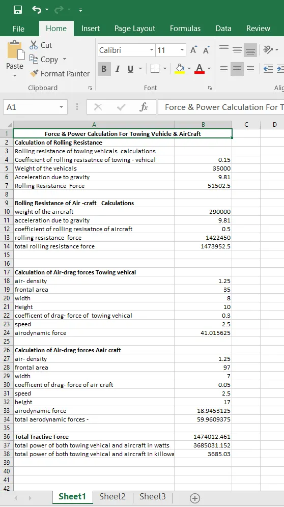
Frr=μrr*m*g
=0.15*35000*9.81
=51502.5 N
In case of air-craft
frr=μrr*m*g
=0.5*290000*9.81
=1422450 N
Total rolling resistance = 51502.5+1422450
=1473952.5 N
Calculating aerodynamic force
=0.5*1.25*35*0.3*(2.5)^2
=41.0156 N
calculating airdrag force for aircraft
fad = 0.5*1.25*97*0.05*(2.5)^2
=18.9453 N
Total aerodynamic force =41.01+18.94
= 59.960 N
Total tractive force = 59.960+1473952.5
=1474012.461 N
Total power drawn by both
pte=fte*v
=1474012.461*2.5
=3685031.152 watts
Total power in kw = 3685.03 kw
Here i have assumed the weight of towing vehicle as 35000 kg and i have taken aircraft as my airplane which is being
towed by the towing vehicle. The weight is 290000 kg.
The other parameters i have assumed are
Coefficient for rolling resistance for towing vehicle =0.15
Coefficient of rolling resistance for aircraft = 0.5
Coefficient of drag for towing vehicle = 0.015
Coefficient of drag for aircraft = 0.05 (here it is low because first the effect of air will be on the vehicle and then it will
affect the aircraft)
speed I have assumed here is 2.5m/s it will be low because the towing vehicle will not run at high speed while pushing/pulling the aircraft
Then I have simply calculated Rolling resistance force and Drag force for both towing vehicle and aircraft and then summed up both to get the total force. So here the total force 1474012.4 N The total power in kW 3685.03KW by multiplying Total force and velocity.
B] Develop the model for the calculated force and power using Simulink.
Now we create simulink model for above calculated force and power in the simulink models first i have create subsystem of rolling resistance force following parameter are puts into its , coefficients of rolling resistance , mass of gravity , mass of vehicals make products of such block with the blocks like constants , and products , display shows the value of force in N same subsystem of aerodynamic force is to be calculated are build while the puts parameter and used blocks like constants , square functions products and display which are connected with each other.
following figure shows the all in one Main simulink models which calculate total forces and power,
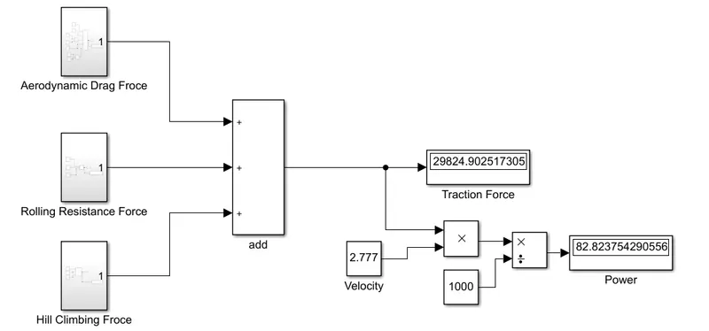
so now above simulink models by openning the subsystem of rolling resisatnce force where rolling resistance are
calculated for both aircraft and towing vehicals and given outputs to additions block calculate total rolling resistance
force and taken display blocks to shows value taken ouputs port of subsystem across the outputs of addition blocks.
now we openning the subsystem of aeroidynamic force where aerodynamics are calculated for both aircraft and
towing vehicals and given outputs to additions block calculate total aerodynamic force and taken display blocks to
shows value taken ouputs port of subsystem across the outputs of addition blocks .
from the simulink model we have created we calculated the value of total power and force . which are displaying the
value in the display blocks .
CASE-7
A] Design an electric powertrain with type of motor, it’s power rating, and energy requirement to fulfill aircraft towing application in Simulink. Estimate the duty cycle range to control the aircraft speed from zero to highest. Make all required assumptions. Prepare a table of assumed parameters. Draw a block diagram of powertrain.
(Hint :DC7 Block)
B] Also, Design the parameters in excel sheet.
Energy =power*time
=from above questions the power calculated is power =3685.03 kw
Time is assumed as 20 minutes which is converted into hours as 0.33 hrs
Time t = 0.33 h
Now,
Energy = 3685.05 *0.33
Energy = 1216.05 kwh
The energy required for 20 min above calculted power is 1216.05 kwh.
Now we have to calculate the input power to drive the duty cycle of the towing vehicle from the above question, those
values are considered based on certain assumptions d towing vehicle,
Duty cycle = Power output/Power input
Where the power input is to be calculated based upon the assumptions of the Motor spar
Input voltage = 700V
Input current = 600A
Now,
Power input = Input voltage x Input current
Power input = 700× 600
Power input = 420000W
Power intput = 420KW
From the calculated values, duty cycle is,
Duty cycle = Power output/Power input
Duty cycle = 368.5/420
Duty Cycle = 0.87
% Duty cycle = 87%
The duty cycle required for towing the vehicle is 87%.
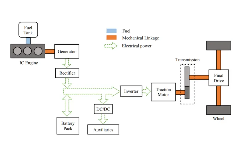
Block Diagram of PowerTrain :-