Week-7 Challenge: DC Motor Control
1. A. Explain a MATLAB demo model named ‘Speed control of a DC motor using BJT H-bridge’.
Solution:
Theory:
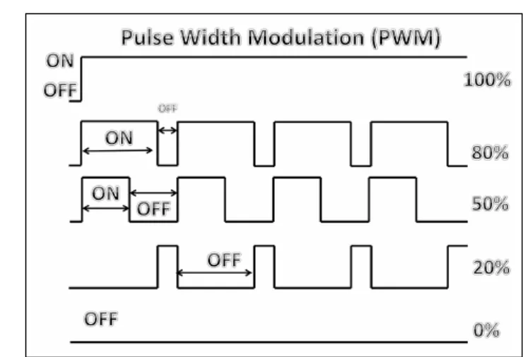
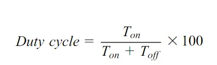
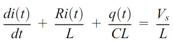
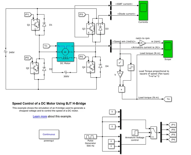
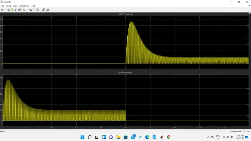
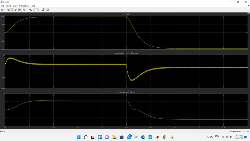
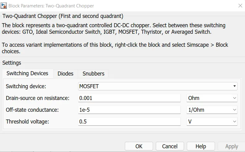
2. To develop a 2-quadrant chopper using Simulink & explain the working of the same with the relevant results
Two-quadrant choppers:
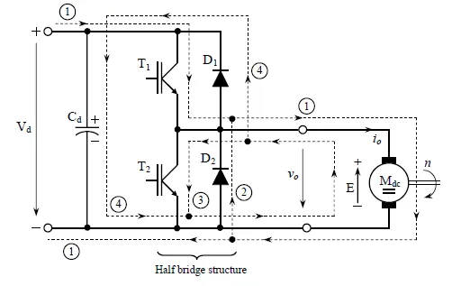
The two-quadrant chopper topology includes two controllable semiconductor devices(transistors) with antiparallel recovery(freewheeling) diodes, forming the well-known bridge leg structure named half-bridge. The way in which the half-bridge structure used for a two-quadrant chopper is connected to the supply DC voltage Vd and to the load(DC motor) is presented in below fig.
Two-quadrant chopper topology:
The control technique of the two transistors is included in the half-bridge structure. So, here in this mentioned only that, the signals for the two power transistors are of a PWM type and complementary. For an easier understanding, the analysis of the operation of the converter will be made under ideal conditions, considering that the power transistor switches instantly. Therefore, the PWM signals can be complementary, without dead time. with this approximation, we obtain the following relationship between the two transistors' duty ratios.
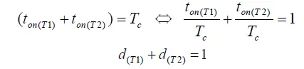
In reality, the power semiconductor devices don't switch instantly. To avoid overlapping conduction of the controllable devices from the half-bridge structure( which is equivalent to a short ckt for the Vd source), in practice are used complementary PWM signals with dead time to control the T1, T2 transistors. The analysis of the dead time influence on the output DC voltage value can be done later for accurate applications such as servo drives where the control precision is essential.
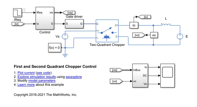
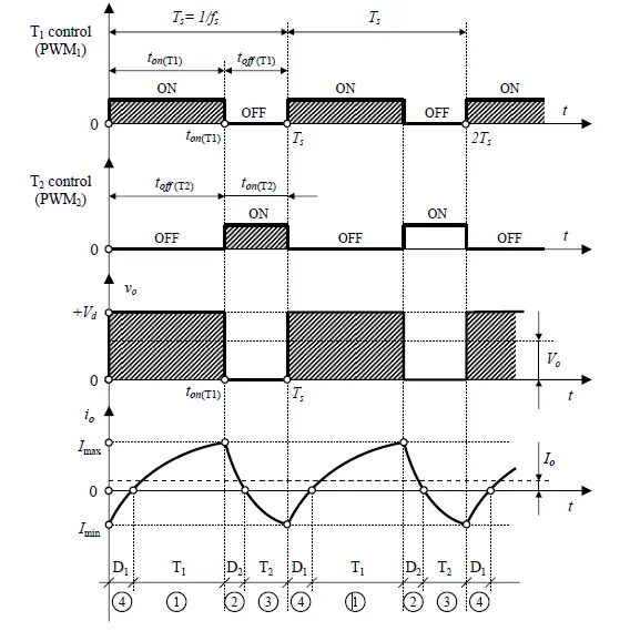
We start the analysis of the converter when the T1 transistor is on and begins to conduct the i0 current that flows through the path. This is a positive current that produces a positive electromagnetic torque at the DC motor level (Tem>0), a torque that helps the movement of the rotor, has the same direction with n speed. During this time interval of the T1 transistor, the supply voltage Vd is applied to the load(DC motor).
V0(t) = Vd ......during the time interval
The output current evolves in time following an increasing exponential in one quadrant chopper. When the T1 transistor is turned off, the i0 current can't further flow through the path. Therefore, it searches for an alternative path, to discharge the inductive energy accumulated in the electromagnetic field of the converter is connected together ( motor terminals are shorted) and the output voltage is zero during the subcycle.
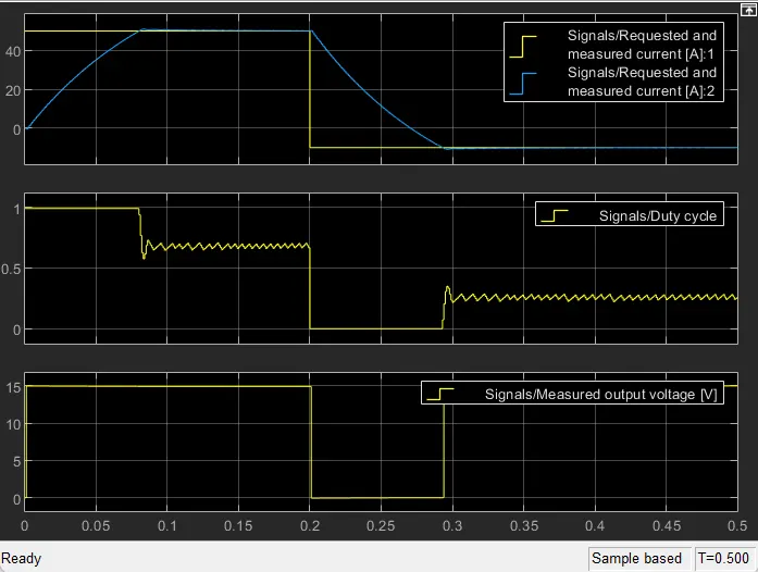
- If I0>0 the electrical machine operates in motor mode producing a positive electromagnetic torque (Tem>0) in the same direction as the rotation speed(n>0). Both the converter and the electric machine operate in the first quadrant.
- If during the DC machine operation with a positive speed (n>0), the duty ratios of the two transistors are suddenly modified, so that to decrease the DC output voltage under the E voltage, from that instant the average current through the DC machine changes the direction, becoming negative.
- A negative current through the DC machine causes a negative electromagnetic torque (Tem<0) in opposition to the rotational movement, with the significance of braking torque.
- The electric machine operates in braking mode as a DC generator in the second quadrant of the mechanical plan n - Tem and the DC/DC converter operates in the second quadrant of the electrical plan V0-I0.
- Depending on the load inductance value, the switching frequency, and the average value of the output current I0 is possible to reduce to two of the four operating subcycles of the converter.
- In the case of the motor acceleration, the average value I0 can increase, so that the minimum values Imin would become positive.
- As a result, the four subcycles will be reduced to subcycles 1 and 2.
- On the other hand, in a dynamic brake mode, the negative magnitude of the I0 can increases so that the maximum value Imax would become negative. In this case, remain the subcycles 3 and 4.
3. BLDC motor
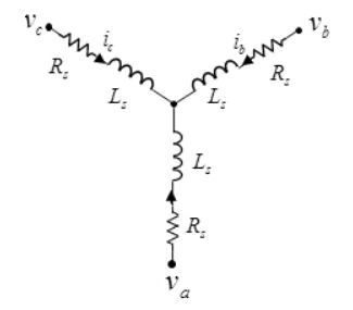
a permanent magnet synchronous machine with a three-phase wye-wound stator. The block has four options for defining the permanent magnet flux distribution as a function of rotor angle. Two options allow for simple parameterization by assuming a perfect trapezoid for the back emf. For simple parameterization, you specify either the flux linkage or the rotor-induced back emf. The other two options give more accurate results using tabulated data that you specify. For more accurate results, you specify either the flux linkage partial derivative of the measured back-emf constant for a given rotor speed.
The figure shows the equivalent electrical circuit for the stator windings.
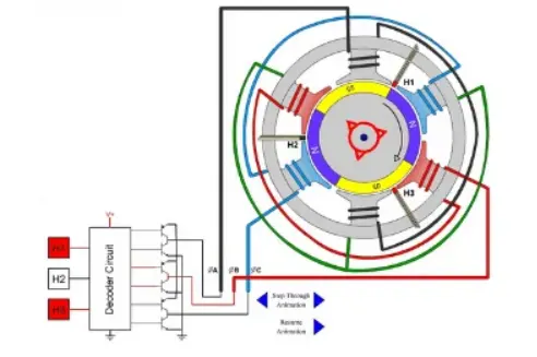
A brushless DC motor (also known as a BLDC motor or BL motor) is an electronically commuted DC motor that does not have brushes. The controller provides pulses of current to the motor windings which control the speed and torque of the synchronous speed.
These types of motors are highly efficient in producing a large amount of torque over a vast speed range. In brushless motors, permanent magnets rotate around a fixed armature and overcome the problem of connecting current to the armature. Commutation with electronics has a large scope of capabilities and flexibility. They are known for smooth operation and holding torque when stationary.
Before explaining the working of a brushless DC motor, it is better to understand the function of a brushed motor. In brushes motors, there are permanent magnets on the outside and a spinning armature that contains an electromagnet is inside. These electromagnets create a magnetic field in the armature when the power is switched on and help to rotate the armature.
The brushes change the polarity of the pole to keep the rotation of the armature. The basic working principle for the brushed DC motor and for the brushless DC motor is the same i.e. internal shaft position feedback.
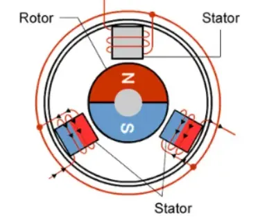
A Brushless DC motor has only two basic parts: the rotor and the stator. The rotor is the rotating part and has rotor magnets whereas the stator is the stationary part and contains stator windings. In BLDC permanent magnets are attached to the rotor and move the electromagnets to the stator. The high-power transistors are used to activate electromagnets for the shaft turns. The controller performs power distribution by using a solid-state circuit.