Week-7 Challenge: DC Motor Control
1. A.
Speed control of a DC motor using BJT H-bridge.
An H bridge cicuit is a simple circuit that helps in control of a DC motor in forward or backward direction. It containing four switching element (BJT)with load at the center and its configuration is like H type.
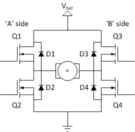
It works like from high voltage/power to ground via following some rules like it can be on when the path of circuit is like (D1 - D4) , simontaniously (D2 - D3) .If it follow the path like (D1 - D2) then it behaves like a low resistance path else like short circuit.Here basically two switches are getting on at same time to complete the circuit from positive to ground.When current starts flowing in the circuit it passes through the motor by which it get energized and starts spinning and it be will ON by switching element (D1 - D4) ON and if we ON the switch(D2 - D3) this will get a negative power by which motor will start rotating in opposite direction.
The bipolar junction transistor (BJT) when used for power switching application it operates as an IGBT(Insulated gate bipolar transistor) while it conducting it produces a forward volatge which developed between collector and emitter of transistor.
In the simulation a DC motor is used with the H bridge , a pulse generator and some basic blocks like scope , gain , constant etc.
Therefore , here we analyzed the basic principle of a DC motor like speed by using a Four BJT with a motor inside called H - bridge.Simulation is carried out and outputs are uploaded below.
B.
Armature current shoot-up:-
As in previous case we have studied that the aremature current gives a positive current for 0.5 sec and after that as motor spinning reversed it gives a negative current .
Here we by changing the the value of pulse width we have summerized some results of armature current.
CASE 1
Pulse width changed from 75 to 50.
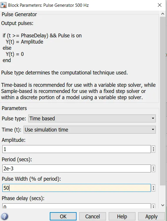
Here the armature current is nearly like 0 upto 0.5 sec and then it give a negative value.
CASE 2
When pulse width is set to 90
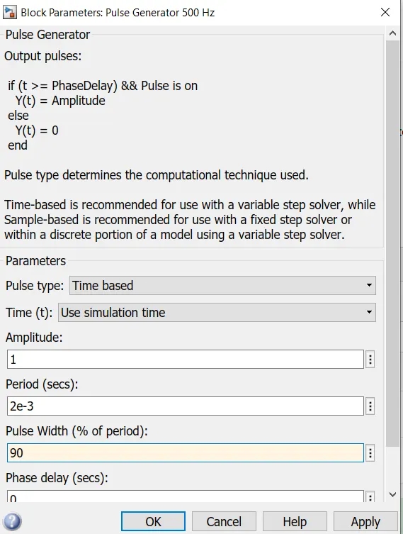
Here the armature current at starting gives a peak value and then decreasing till 0.5 sec then it gives a negative in current direction.
Outputs are uploade below.
Hence, here we basically studied the different different armature current of a dc motor using BJT H - bridge .
C.
The Four-Quadrant Chopper DC Drive (DC7) block:-
This block represnts a four quadrant DC supplied chopper drive for DC motors.Its main advantage is it can operate in all four quadrants.As here high frequency DC-DC converters are used thats why a lower armature current ripple is obtained and it is a complex system.
The Four-Quadrant Chopper DC Drive (DC7) block uses these blocks for electric drives
1.Speed controller
2.switch
3.chopper
4.speed controller
The four quadrant conditions are like in quadrant 1 - forward motoring
quadrant 2 - reverse breaking
quadrant 3 - reverse motoring
quadrant 4 - forward breaking
Comparison between H bridge and four quadrant chopper :-
1.All possible mode of switching in four quadrant while in H bridge we can ON two switches simotaniously.
2.Type of Operation is more in four quadrant chopper than H bridge.
3.maintainance is more than H bridge system.
4.Efficiency is high in four quadrant chopper than H bridge.
5.We can change the signal easily in H bridge.
6.Four quadrant chopper used in small areas like drone , robotics .
7.Both the models are recently using in EV industries.
8.Power flow is same like both from source to load and vice versa.
Hence, above we study two systems which have some similarities and difference between them .
2.
2-quadrant chopper :-
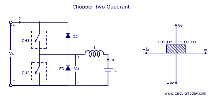
Two-quadrant chopper is also called as class - C chopper where as it is the parallel combination of class - A and class - B chopper. In this chopper we will always get positive average voltage but the load can be positive or negative.
It works like in the first quadrant where voltage and current are positive , then its chopper 1 (CH1) and Diode (FD) starts conducting and the current flow across the inductor and as it folllow its principle it stores energy. after the chopper going to off position the energy stored by in inductor starts flowing in load and diode FD and here power flows from source to load . Here the voltage across load is equal to the voltage of the source. It is also called the forward motoring mode .
In the second quadrant chopper 2 (CH2) and diode(D2) are turning ON as here the current flows from the inductor as it stores energy. then if CH2 is getting OFF then the power flows through D2 to the source so it is called here power flows from load to source. It is called reverse breaking mode .
Simulations is performed and results are uploaded below.
Here we simulated the model by giving input as DC voltage value =24 V at source and 12 V at load , pulase generator amplitude value 10 pulse width 50, duration 0.02 s and uses some mosfet , diode block to complete the circuit and by scope block the current and voltage are measured. WE observe here that current can be positive or negative but voltage is always positive.
OUTPUT:-
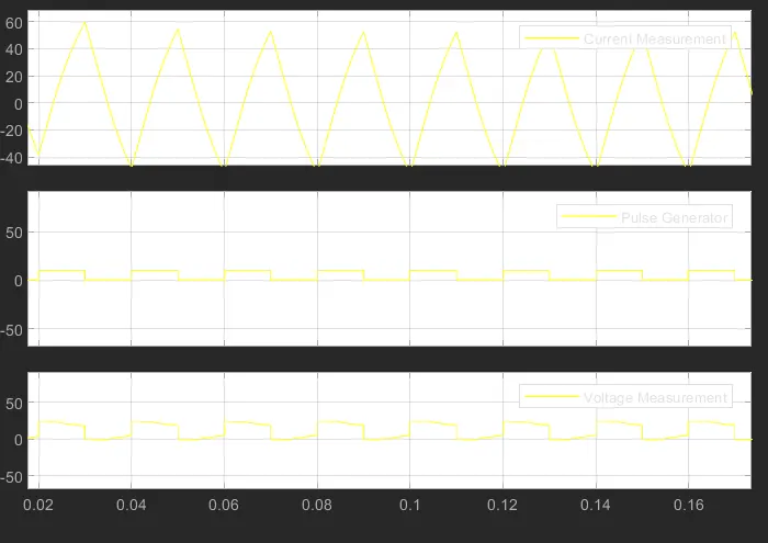
Hence ,here we observe two quadrant chopper and its properties ,we simulate the model and outputs are recorded.
3.
Operation of BRUSHLESS DC MOTOR (BLDC motor) :-
> This motor consisting of a stator an d rotor where as overall control or the excitation process is controlled by some contol unit (we can give input over there) . As its name suggests it dont have brushes to collect the output so called BRUSHLESS DC MOTOR .
> The big difference between brush and brushles motor is the commutator with an electrical circuit. There are three types of BLDC motor 1 - Single phase BLDC motor
2 - Double phase BLDC motor
3- Three phase BLDC motor
>The construction of the stastor is nearly same as induction motor. The stastor winding are connected to that contolled unit and it energzied the power . These are mainly connected in star or delta connection. Mainly made of up steel laminations .
>Rotor are made of up parmagent magnet and the no of poles can be varied here. It tries to catch the electomagnet of the stator winding and by doing so its starts rotating.It gives maximum torque at starting condition.
>Here basically a DC current is energzied in the winding of stator by which it induces some magnetic field and the poles of the electromagnet are decided by the direction of current flow.
>After that it attracts the permagnet magnet of rotor by which a rotational force in generated between stator and the rotor. To increase efficiency we can energize two windings.Mostly HALL sensor is used to sense the rotor position.
>For no brush less noisy produced.
>It has some more efficiency than the with brush motors.
>ADVANTAGES:-
>>Less maintanance .
>>Less noisy and higher speed range.
>>Long life.
>>Light weight than brushed motor.
>DISADVANTAGES:-
>>Mostly costly.
>>Many sensor required.
>>Complex circuit.
>Commonly used as computer hard drives , pumps , fans , washing machines , electrical vehicles etc.