Week-7 Challenge: DC Motor Control
Q.
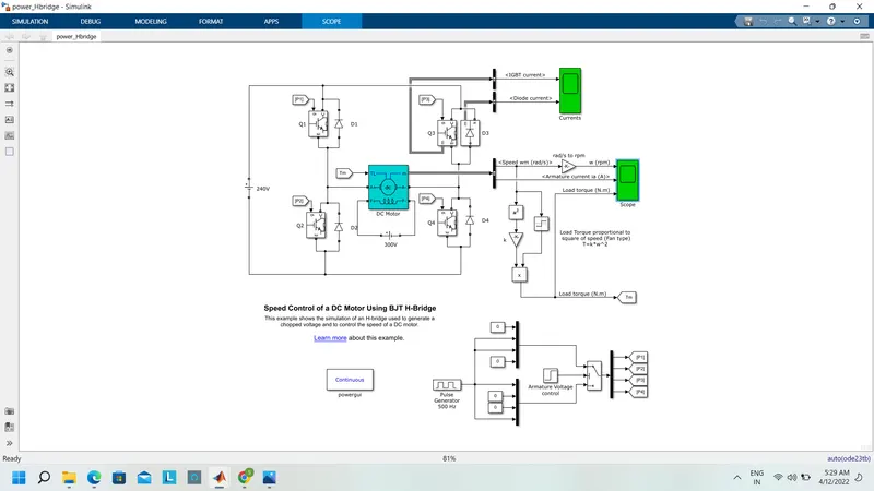
1. A. Explain a MATLAB demo model named ‘Speed control of a DC motor using BJT H-bridge’.
B. Comment on the armature current shoot-up from the scope results.
C. Refer to the help section of ‘The Four-Quadrant Chopper DC Drive (DC7) block’. Compare it with the H-bridge model.
Ans:-
Speed of a DC motor using BJT H-bridge
H-bridge:-in In general, an H-bridge is a rather simple circuit, contacting, four switching elements, with the load at the center, in an H-like configuration.
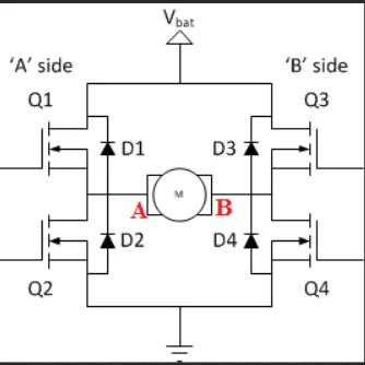
The basic operation of the H-bridge circuit diagram is given below:-
motor rotates in a forward direction:-
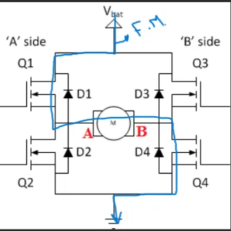
When the positive gate signal is given the switches Q1 and Q4 are turned on and the motor rotates in the forward direction .D1 and D4 are in condition .during charging of the positive to the negative period the D1and D4 are in on condition at that time the switch Q1 and Q4 are off condition.
A motor rotates in a reverse direction:-
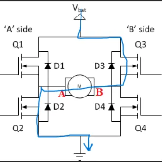
When the positive gate signal is given the switches Q3 and Q2 are turned on and the motor rotates in the reverse direction .D3 and D2 are in condition .during charging of the positive to the negative period the D3 and D2 are in on condition at that time the switch Q3 and Q2 are off condition.
Simulink model
When used for power switching applications, the Bipolar Junction Transistor (BJT) operates as an IGBT. When it is conducting (BJT operating in the saturated region), a forward voltage Vf is developed between collector and emitter (in the range of 1 V). Therefore, the IGBT block can be used to model the BJT device.
DC motor used in the Simulink model
The IGBT block does not simulate the gate current controlling the BJT or IGBT. The switch is controlled by a Simulink® signal (1/0). The DC motor uses the preset model (5 HP 24V 1750 rpm). It simulates a fan type load (where Load torque is proportional to the square of speed). The armature means voltage can be varied from 0 to 240 V when the duty cycle (specified in the Pulse Generator block) is varied from 0 to 100%.
The H-bridge consists of four BJT/Diode pairs (BJT simulated by IGBT models). Two transistors are switched simultaneously: Q1 and Q4 or Q2 and Q3. When Q1 and Q4 are fired, a positive voltage is applied to the motor, and diodes D2-D3 operate as free-wheeling diodes when Q1 and Q4 are switched off. When Q2 and Q3 are fired, a negative voltage is applied to the motor, and diodes D1-D4 operate as free-wheeling diodes when Q2 and Q3 are switched off.
Pulse width Modulation(PWM):-
pulse-width modulation (PWM) is a modulation technique that generates variable-width pulses to represent the amplitude of an analog input signal. The length of time that a pulse in a given state (HIgh/low) is the 'width of a pulse wave .here the term comes to the duty cycle which represents in percentage values.
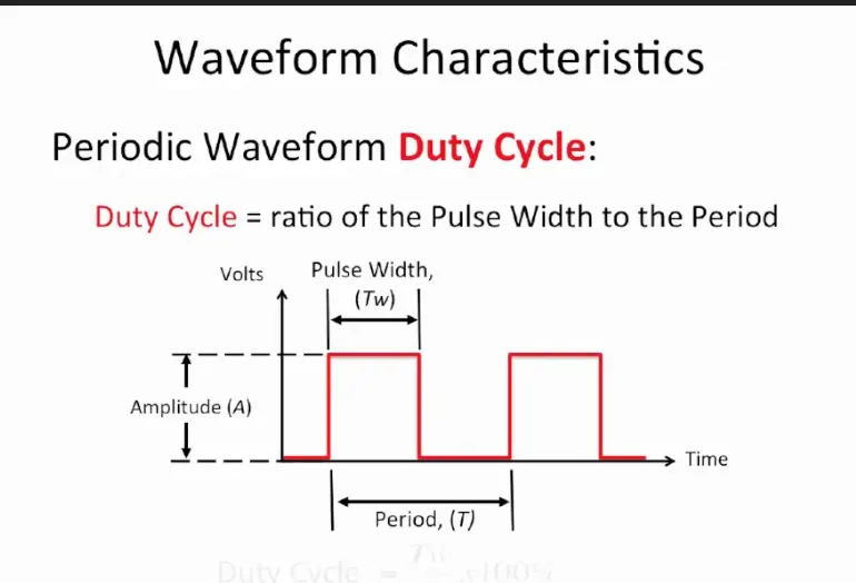
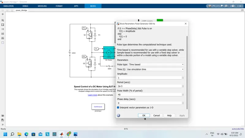
The pulse generator is given by a pulse width of 75% and a period of 2e-3seconds. the motor parameters of the torque and fiend voltage and armature voltage are taken as the default value of the model.
B. Comment on the armature current shoot-up from the scope results.
Click run this modulation
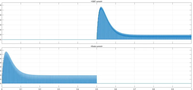
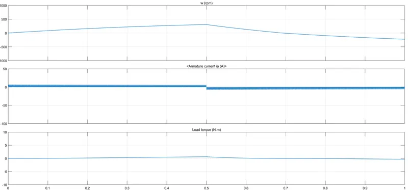
From the waveform, I noticed that the 0 to 0.5 time the IGBT current is zero and the diode current is on after the 0.5 to 1 time the IGBT starts current flow the diode current is zero.
Now,
we will take the output waveform of the load torque, armature current, and speed
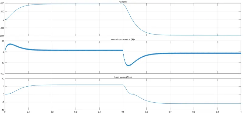
From the above the armature current shoot-up at the starting of the armature current a sudden rise in the waveform we had noticed.
TO reduce the sudden rise in the armature current we will the reduce the duty cycle of the pulse width modulation from (75 to 50 %)
now, 40% pulse width modulation
scope:-
C. Refer to the help section of ‘The Four-Quadrant Chopper DC Drive (DC7) block’. Compare it with the H-bridge model.
A chopper uses the high speed to connect and disconnect from a source load. A fixed DC voltage is applied intermittently to the source load by continuously triggering the power switch ON/OFF. The period for which the power switch stays ON or OFF is referred to as the chopper’s ON and OFF state times, respectively.
Choppers are mostly applied in electric cars, conversion of wind and solar energy, and DC motor regulators.
Symbol of a Chopper
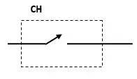
For Quadrant chopper
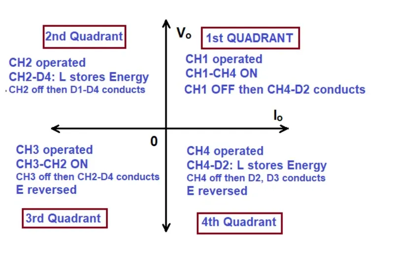
block diagram for chopper
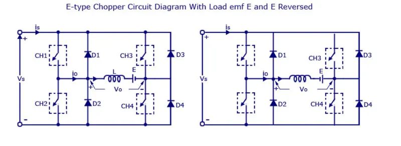
Type E or fourth quadrant chopper consists of four semiconductor switches and four diodes arranged in antiparticle. the 4 choppers are numbered according to which quadrant they belong .thier operation will be in each quadrant and the corresponding chopper only be active in its quadrant.
The Four-Quadrant Chopper DC Drive (DC7) block
Simulink model
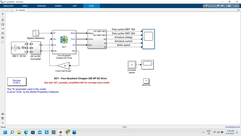
scope:-
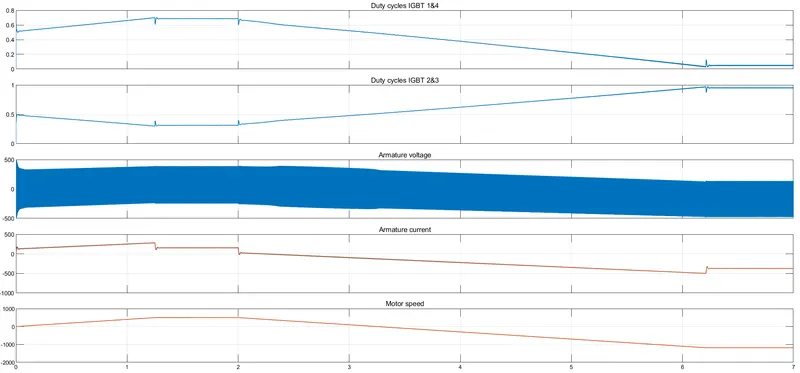
The 200 HP DC motor is separately excited with a constant 150 V DC field voltage source. The armature voltage is provided by an IGBT converter controlled by two PI regulators. The converter is fed by a 515 V DC bus obtained by rectification of a 380 V AC 50 Hz voltage source. To limit the DC bus voltage during dynamic braking mode, a braking chopper has been added between the diode rectifier and the DC7 block.
The first regulator is a speed regulator, followed by a current regulator. The speed regulator outputs the armature current reference (in p.u.) used by the current controller to obtain the electromagnetic torque needed to reach the desired speed. The speed reference change rate follows acceleration and deceleration ramps to avoid sudden reference changes that could cause armature over-current and destabilize the system. The current regulator controls the armature current by computing the appropriate duty ratios of the 5 kHz pulses of the four IGBT devices (Pulse Width Modulation). For proper system behavior, the instantaneous pulse values of IGBT devices 1 and 4 are opposite to those of IGBT devices 2 and 3. This generates the average armature voltage needed to obtain the desired armature current. To limit the amplitude of the current oscillations, a smoothing inductance is placed in series with the armature circuit.
Simulation
Before starting the simulation, set the initial bus voltage to 515 V via the GUI block ('The Initial States Setting' button and 'Cbus' variable).
Start the simulation. You can observe the motor armature voltage and current, the four IGBT pulses, and the motor speed on the scope. The current and speed references are also shown.
The motor is coupled to a linear load, which means that the mechanical torque of the load is proportional to the speed.
The speed reference is set at 500 rpm at t = 0 s. Observe that the motor speed follows the reference ramp accurately (+400 rpm/s) and reaches a steady-state around t = 1.3 s.
The armature current follows the current reference very well, with a fast response time and small ripples. Notice that the current ripple frequency is 5 kHz.
At t = 2 s, the speed reference drops to -1184 rpm. The current reference decreases to reduce the electromagnetic torque and causes the motor to decelerate with the help of the load torque.
At t = 2.2 s, the current reverses to produce a braking electromagnetic torque (dynamic braking mode). This causes the DC bus voltage to increase.
At t = 3.25 s, the motor reaches 0 rpm and the load torque reverses and becomes negative. The negative current now produces an accelerating electromagnetic torque to allow the motor to follow the negative speed ramp (-400 rpm/s). At t = 6.3 s, the speed reaches -1184 rpm and stabilizes around its reference.
comparing
The Four-Quadrant Chopper DC Drive (DC7) block. H-bridge model.
1) the motor can be operated in all the four different models in this model have only two models forward
(forward motoring, reverse motoring, forward barking, and forward and reverse by changing the direction of
reverse braking) motor
2).in this the vehicle control is the better in this the vehicle control is less
3). Regenerative braking can be achieved in this regenerating Regenerative braking can be achieved less
braking is not possible.
*****************************************************************************************
Q 2. Develop a 2-quadrant chopper using Simulink & explain the working of the same with the relevant results. (Refer to the article - Multiquadrant operation of the motor )
Ans;-
2-Quadrant chopper
In the 2-quadrant chopper one-two type i,) class -c ii) class-d
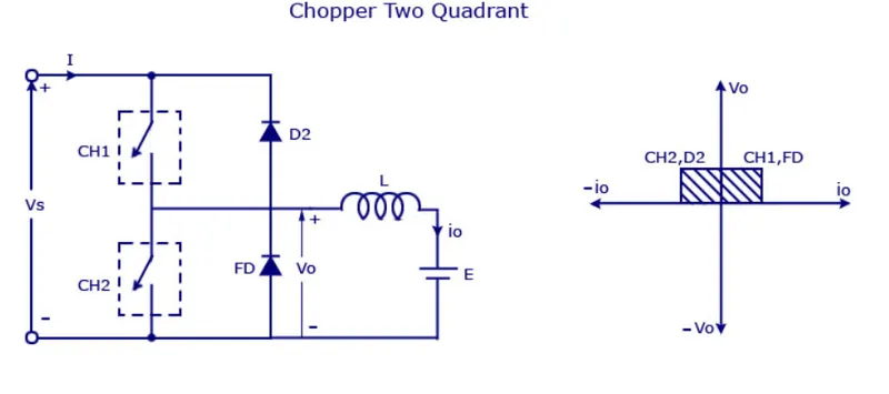
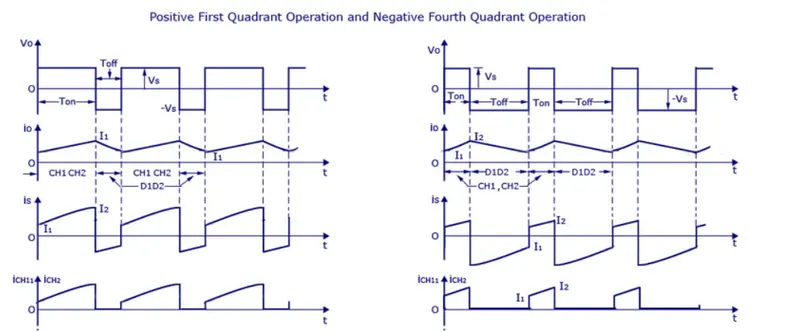
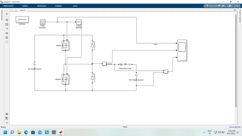
Sometimes a chopper may be required to provide a two-quadrant operation by retaining the current direction in both motoring and braking modes. Such a Two Quadrant Chopper is shown in Fig. and its waveforms in. The chopper permits a change in the polarity of terminal voltage keeping the direction of current constant. Fig S1 and S2 are the choppers working as electronic switching and D1 and D2 are the feedback diodes. Assuming continuous conduction, both S1 and S2 operate simultaneously.
When they are ON, the load current Id increases, with the rate of rising depending upon the back emf and torque of the machine. When they are OFF, the load current is fed to the supply through the diodes D1 and D2. The current decreases in this stage. From Fig, it is clear that the load voltage is effectively negative when the diodes conduct. The average value of the output voltage of the chopper
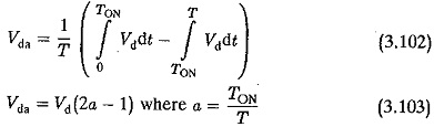
Vidada is zero for a = 0.5, the output voltage is an ac waveform with an average voltage equal to zero. For a > 0.5 the average value of the dc voltage is negative. The chopper works in the regenerating braking. The power flows from the load to the supply and the dc machine operates as a generator. For control ratios a c 0.5, the operation is similar to the inversion of a line commuted converted (α > 90°). For a > 0.5 the chopper has a normal operation. The power flows from the supply to the load. This operation of the chopper is similar to the rectification of a line commutated converter (α < 90°). For, a = 0.5 the load voltage is zero. The control characteristic of a two-quadrant chopper is shown in Fig.
waveform
Simulink model:-
scope:-
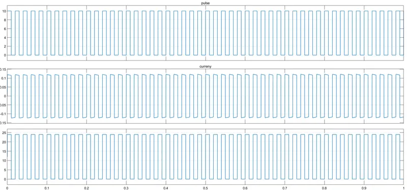
The output of the current waveform is in a positive direction and the voltage waveform is positive and the negative half cycle
****************************************************************************
Q.
3. Explain in a brief the operation of the BLDC motor.
Ans:-
A Brushless DC Motor, BLDC accomplishes commutation electronically using rotor position feedback to determine when to switch the current. The BLDC motor is electrically commutated by power switches instead of brushes. The structure of the Brushless DC Motor, BLDC is shown in the figure below.

In simple words, a BLDC has no brushes and commutator for having unidirectional torque rather integrated inverter/switching circuit is used to achieve unidirectional torque. That is why these motors are, sometimes, also referred to as Electronically Commutated Motors.
Construction of a BLDC Motor:
Like any other electric motor, a BLDC motor also has a stator and a rotor. Here we will consider Stator and Rotor each separately from a construction point of view.
BLDC Stator:
There are three types of the BLDC motor:
- Single-phase
- Two-phase
- Three-phase.
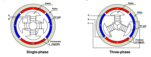
The stator for each type has the same number of windings. The single-phase and three-phase motors are the most widely used. The simplified cross-section of a single-phase and a three-phase BLDC motor is shown in the figure below. The rotor has permanent magnets to form two magnetic pole pairs and surrounds the stator, which has the windings.
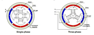
A single-phase motor has one stator winding wound either clockwise or counter-clockwise along each arm of the stator to produce four magnetic poles as shown in the above figure.
A three-phase BLDC motor has three windings. Each phase turns on sequentially to make the rotor revolve.
Rotor:
A rotor consists of a shaft and a hub with permanent magnets arranged to form between two to eight pole pairs that alternate between the north and south poles. The figure below shows cross-sections of three kinds of magnets arrangements in a rotor.
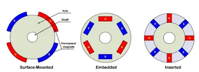
How Does A Brushless DC Motor Work?
BLDC Motor operation is based on the attraction or repulsion between magnetic poles. Using the three-phase motor as shown in the figure below, the process starts when current flows through one of the three stator windings and generates a magnetic pole that attracts the closest permanent magnet of the opposite pole.
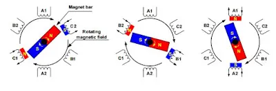
The rotor will move if the current shifts to an adjacent winding. Sequentially charging each winding will cause the rotor to follow in a rotating field. The torque in this example depends on the current amplitude and the number of turns on the stator windings, the strength and the size of the permanent magnets, the air gap between the rotor and the windings, and the length of the rotating arm.
Animation for a better understanding of BLDC Motor:
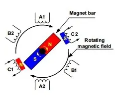
Advantages of BLDC Motor:
Compared with a brushed DC motor or an induction motor, the BLDC motor has many advantages:
- Higher efficiency and reliability
- Lower acoustic noise
- Smaller and lighter
- Greater dynamic response
- Better speed versus torque characteristics
- Higher speed range
- Longer life