Week -2
- Make a Simulink model of Doorbell using a solenoid block with the following details:
aim:-
To make a Simulink model of a doorbell using solenoid block
BLOCK DIAGRAM:-
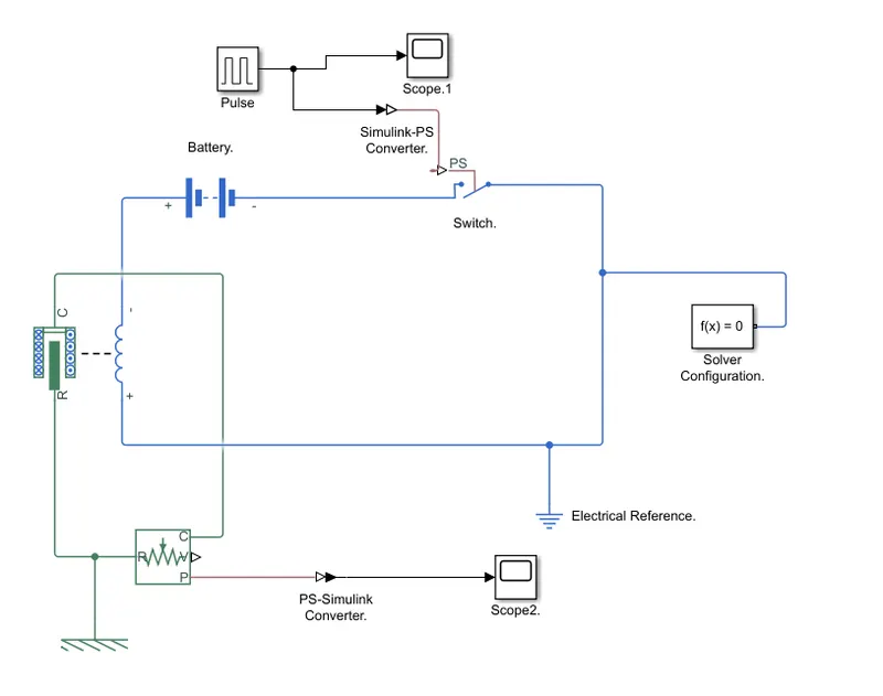
Simulink model explanation
The pulse generator is used to create square wave pulses at regular intervals. The block waveform parameters Amplitude, pulse width, period, and phase delay determine the shape of the output waveform.

- The switch block used is controlled by an external physical signal. if the external signal then the threshold parameter the switch is closed, otherwise, the switch is open
- The positive terminal of the switch is connected to the switch and the negative terminal is connected to the electrical reference
- The Solenoid block is connected with the switch and battery and we will get a complete electrical circuit. port C
is connected with mechanical reference - The ideal translational sensor is connected with solenoid block R to observe the movement of the plunger,
- The scope is connected with the ideal translational sensor to get the output
- Ps -Simulink converter is used to convert the physical signal to Simulink signal
Solver Configuration: Each physical network represented by a connected simscape block requires solver information for
simulation
output
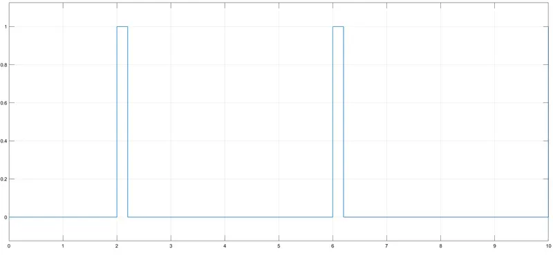
scope1 output
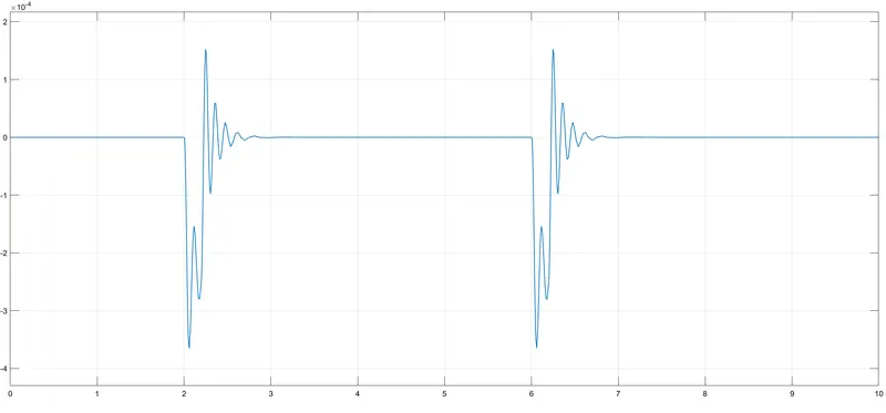
scope2 output
Result:-
The Simulink model of Doorbell using a solenoid block using done plot successfully.
===============================================================================
2. Use a thermistor to sense the temperature of a heater & turn on or turn off the fan as per the below conditions:
Temperature source: 20 °C from 0 to 10 seconds, 27 °C from 10 to 30 seconds, 23 °C from 30 to 50 seconds
Fan conditions: ON if the temperature above 25 °C, OFF otherwise
ans:-
Aim:-
To use a thermistor to sense the temperature of a heater & turn on or Turn off the fan.
Given data:-
Temperature source: 20 °C from 0 to 10 seconds, 27 °C from 10 to 30 seconds, 23 °C from 30 to 50 seconds
Fan conditions: ON if the temperature above 25 °C, OFF otherwise
Simulink model block diagram
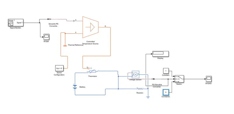
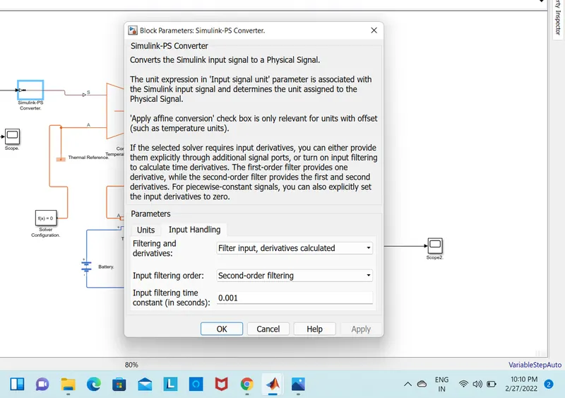
Simulink model explanation
- At point1,time=0sec,temperature=293k
- At point2,time=10sec,temperature=293k
- At point3,time=10sec,temperature=300k
- At point4,time=30sec,temperature=300k
- At point5,time=30sec,temperature=296k
At point6,time=50sec,temperature=296k
- controlled temperature source represents an ideal source of thermal energy, that can maintain a controlled temperature difference
regardless of the heat flow rate. - A thermistor is a type of resistor whose resistance is based upon temperature.
- A-line resistor is used to control the amount of current from the battery.
- The voltage sensor is used to convert the voltage measured between two points into a physical signal.
- Voltage source which represents dc or ac.
- electrical reference block is given.
OUTPUT:
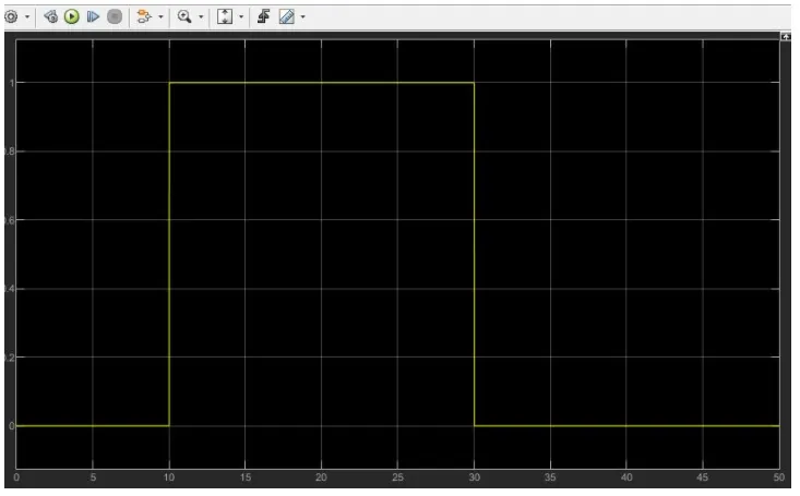
RESULT:-
for 0 to 10s fan is OFF condition because the temperature is 293k which is below the threshold of 298k. after 10s temperature goes to 300k
then the switch will be in ON condition as the temperature exceeds 298k. after the 30s a fan will turn oFF as the temperature come down to 296k.