Week - 4
Q.1.Implement control logic of a “washing machine” using Stateflow as per given sequence:
ans:-
AIM:-
To implement the control logic of a washing machine using Stateflow in Simulink.
objective:-
1. TO implement the control logic of the washing machine using Stateflow as per the given sequence
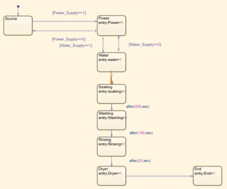
a) if a power supply is available, the system gets activated.
b)if the Water supply is not available, stop the process & indicate through the LED.
c)Soaking time should be 200s followed by Washing time of 100s
d) Then rising happened for next 20s &dryer runs for 50s.
after all the processes have been completed turn on the finished LED
MODEL:-
the file which contains the model is attached to this report
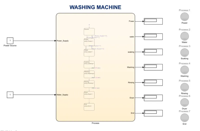
pictorial REpresentation of Block diagram
THE Representation of a block diagram:-
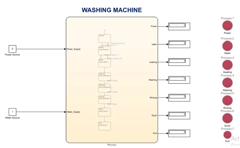
case:-1, if the power source =0, power supply not available does not work system
case:-2, if the power source =1 & water =1, the power system turn on the system is an active state
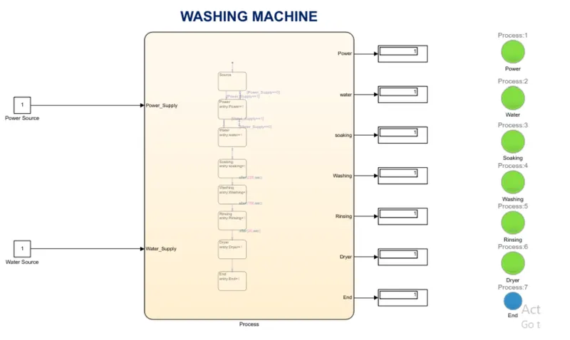
RESULT:-
The completed washing machine flowchart diagram using Simulink.
****************************************************************************
2. Make a Simulink chart for the “Gear shift” logic as per the below conditions:
Speed Range(km) Gear
0 to 15 1
16 to 25 2
26 to 40 3
41 to 60 4
Above 61 5
Give speed input while the simulation is running & display the gear number.
ans:-
AIM
Mechanical devices that enable the drive to engage gears in such a way as to obtain the desired transmission ratio are called shifting mechanism
EXPLANATION FOR GEAR SHIFTING MECHANISM USING SIMULINK
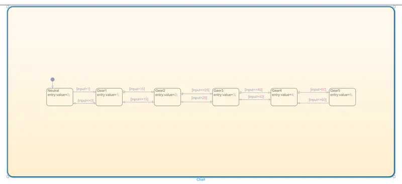
Step1: Create a chart and enter the given conditions for gear shifting
Given conditions.
Speed Range(km) Gear
0 to 15 1
16 to 25 2
26 to 40 3
41 to 60 4
Above 61 5
modal daigram :-
Step:-2
After entering the input conditions in the chart, Go to the symbols pane and assess the given
variable(example:input data,output data )
Step:-3
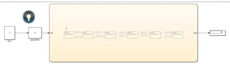
Connect the Silver Gain to vary the speed while the simulation is running.
Step:-4
Create Constant and giving value 1 and for turning on &off
Step:-5
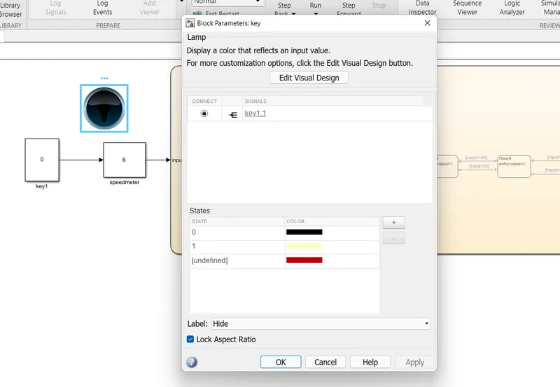
create a Lamp to indicate the power is on or off
Step:-6
Use display Block to display the gear position
GEARBOX DIAGRAM:-
CASE-1;
IF the key =0; the lamp indicates the turn of gaer the system is not active gear.
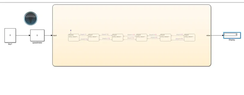
case-2:
IF the key =1; the power will turn on, lamp indicates the green color signal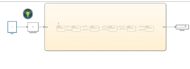
case-3:
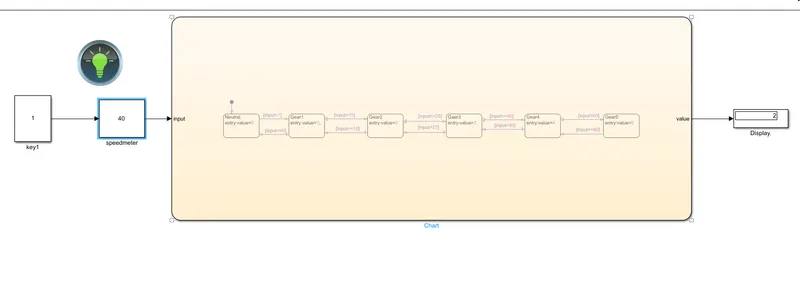
varying the speed(parameter ) speedometer 40km/hr.
RESULT
The completed of GEAR mechanism and speed using Simulink flowchart .