Week-7 Challenge: DC Motor Control
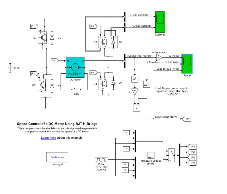
1. A. Explain a MATLAB demo model named ‘Speed control of a DC motor using BJT H-bridge’.
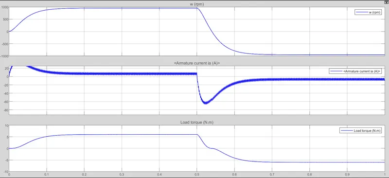
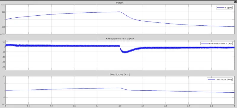
B. Comment on the armature current shoot-up from the scope results.
C. Refer to the help section of ‘The Four-Quadrant Chopper DC Drive (DC7) block’. Compare it with the H-bridge model.
A: Speed Control of a DC motor using BJT H-bridge:
Bipolar Junction Transistor (BJT) operates as an IGBT when used for power switching applications. A forward voltage Vf is developed between collector and emitter during conduction. IGBT blocks can be used to model the BJT device. IGBT block doesnot simulate the gate current controlling the BJT or IGBT. The dc motor uses a preset model (5 HP 24V 1750rpm). It simulates a fan type load. H bridge consists of 4 BJT/diode pairs. 2 transistors are switched simultaneously. Q1 & Q4 or Q2 &Q3 together. When Q1 & Q4 are triggered a positive voltage is applied to the motor and diodes D2-D3 operates as free wheeling diodes when Q1 & Q4 are switched off. When Q2 & Q3 are triggered a negetive voltage is applied to the motor and diodes D1-D4 operates as free wheeling diodes when Q2- Q3 are switched off.
SIMULINK MODEL:
B: Motors require a certain output in watts in order to function, and this is the result of a voltage multiplied by amps. So when voltage falls, resistance scales up in order to supply the difference, and the motor will also draw more current.
Consider the Simulink model above keeping all the initial parameters as same perform simulation;
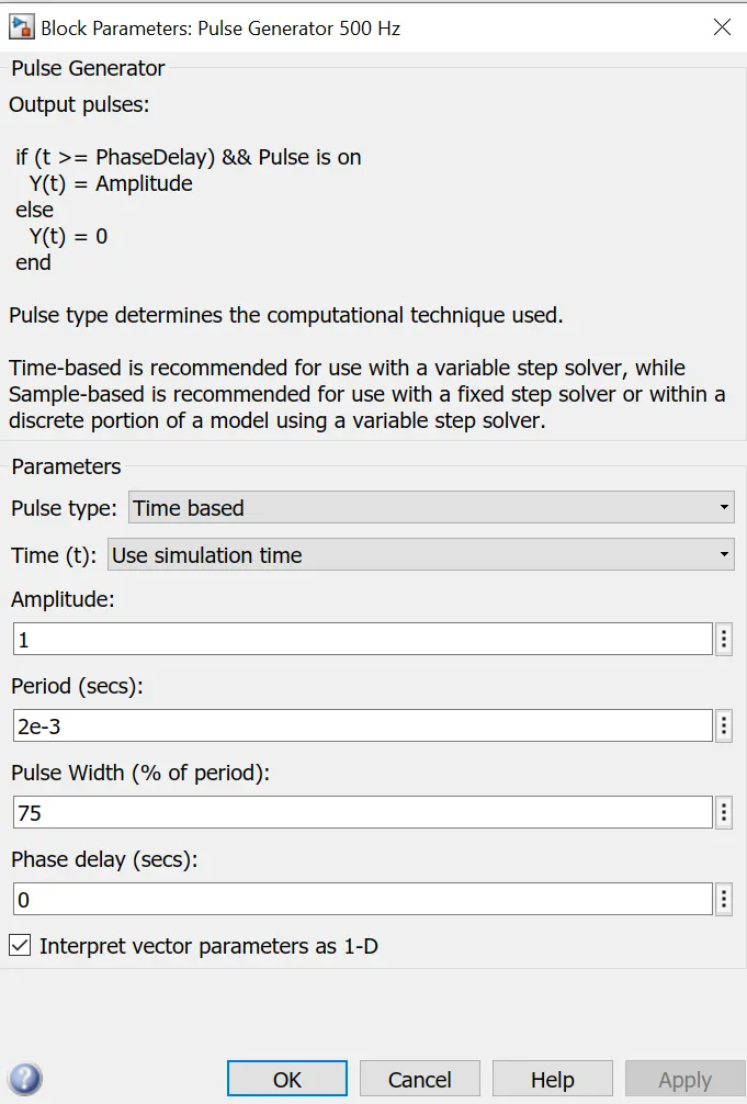
Output for 75% pulse width:
Output for 55% pulse width: Armature current dip reduces
Output for 30% pulse width: Shooting of current almost disappears
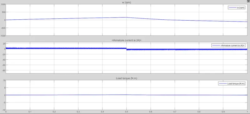
DC resistance of rotor winding is minimum, when power is switched on it will draw a very high current equal to V/R and if the motor is not rotating then the winding will burn out. When motor starts rotating then a back emf is built which opposes the input emf and resultant emf will be small to maintain the current within the limit. Inrush current of dc motor is given by I=(V-E)/R where R is the armature resistance, V is the terminal voltage, E is the back emf. For a dc motor the armature resistance is very small so the inrush current will be very high and as the motor starts rotating back emf is developed and current value goes down.
C: The Four-Quadrant Chopper DC Drive (DC7) block:
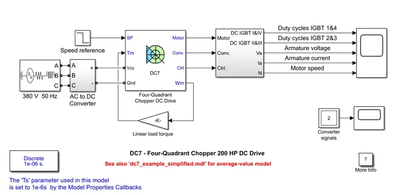
The 200 HP DC motor is separately excited with a constant 150 V DC field voltage source. The armature voltage is provided by an IGBT converter controlled by two PI regulators. The converter is fed by a 515 V DC bus obtained by rectification of a 380 V AC 50 Hz voltage source. In order to limit the DC bus voltage during dynamic braking mode, a braking chopper has been added between the diode rectifier and the DC7 block.
The first regulator is a speed regulator, followed by a current regulator. The speed regulator outputs the armature current reference (in p.u.) used by the current controller in order to obtain the electromagnetic torque needed to reach the desired speed. The speed reference change rate follows acceleration and deceleration ramps in order to avoid sudden reference changes that could cause armature over-current and destabilize the system. The current regulator controls the armature current by computing the appropriate duty ratios of the 5 kHz pulses of the four IGBT devices (Pulse Width Modulation). For proper system behaviour, the instantaneous pulse values of IGBT devices 1 and 4 are opposite to those of IGBT devices 2 and 3. This generates the average armature voltage needed to obtain the desired armature current. In order to limit the amplitude of the current oscillations, a smoothing inductance is placed in series with the armature circuit.
Model:
Simulation:
Before starting the simulation, set the initial bus voltage to 515 V via the GUI block ('Initial States Setting' button and 'Cbus' variable).
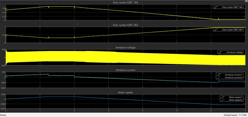
Start the simulation. You can observe the motor armature voltage and current, the four IGBT pulses and the motor speed on the scope. The current and speed references are also shown.
The motor is coupled to a linear load, which means that the mechanical torque of the load is proportional to the speed.
The speed reference is set at 500 rpm at t = 0 s. Observe that the motor speed follows the reference ramp accurately (+400 rpm/s) and reaches steady state around t = 1.3 s.
The armature current follows the current reference very well, with fast response time and small ripples. Notice that the current ripple frequency is 5 kHz.
At t = 2 s, speed reference drops to -1184 rpm. The current reference decreases to reduce the electromagnetic torque and causes the motor to decelerate with the help of the load torque.
At t = 2.2 s, the current reverses in order to produce a braking electromagnetic torque (dynamic braking mode). This causes the DC bus voltage to increase.
At t = 3.25 s, the motor reaches 0 rpm and the load torque reverses and becomes negative. The negative current now produces an accelerating electromagnetic torque to allow the motor to follow the negative speed ramp (-400 rpm/s). At t = 6.3 s, the speed reaches -1184 rpm and stabilizes around its reference.
Output:
H Bridge model:
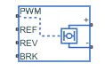
The H-Bridge block represents an H-bridge motor driver. The block has the following two Simulation mode options:
PWM — The H-Bridge block output is a controlled voltage that depends on the input signal at the PWM port. If the input signal has a value greater than the Enable threshold voltage parameter value, the H-Bridge block output is on and has a value equal to the value of the Output voltage amplitude parameter. If it has a value less than the Enable threshold voltage parameter value, the block maintains the load circuit using one of the following three Freewheeling mode options:
- Via one semiconductor switch and one freewheeling diode
- Via two freewheeling diodes
- Via two semiconductor switches and one freewheeling diode
The first and third options are sometimes referred to as synchronous operation.
The signal at the REV port determines the polarity of the output. If the value of the signal at the REV port is less than the value of the Reverse threshold voltage parameter, the output has positive polarity; otherwise, it has negative polarity.
The current will be smooth if the PWM frequency is large enough. Synchronous operation where freewheeling is via a bridge arm back to the supply also helps smooth the current. For cases where the current is not smooth, or possibly discontinuous (that is, it goes to zero between PWM cycles), use the Unsmoothed or discontinuous option. For this option, you must also provide values for the Total load series resistance, Total load series inductance, and PWM frequency. During simulation, the block uses these values to calculate a more accurate value for H-bridge output voltage that achieves the same average current as would be present if simulating in PWM mode.
External power supply:
To model the demands placed on the DC supply, you can choose to expose the power supply ports of the H-Bridge block by setting the Power supply parameter to External. If the power supply ports are exposed, then only PWM simulation mode is supported.
Thermal port:
The block has an optional thermal port, hidden by default. To expose the thermal port, right-click the block in your model, and then from the context menu select Simscape > Block choices > Show thermal port. This action displays the thermal port H on the block icon, and adds the Temperature Dependence and Thermal Port parameters.
COMPARISON:
- Four quadrant chopper can work in 4 quadrants - forward motoring, forward braking, reverse motoring and reverse braking. H-bridge can operate only in 2 quadrants.
- Efficiency is performance is better with 4 quadrant chopper than H bridge.
- Regenerative braking is not possible in H bridge but possible in chopper.
- Maintanance cost is less for 4 quadrant chopper.
- A H-bridge is an electronic circuit that switches the polarity of a voltage applied to a load. These circuits are often used in robotics and other applications to allow DC motors to run forwards or backwards.
- A servo system capable of controlling velocity and torque in both positive and negative directions is known as having 4 quadrant operation.
2. Develop a 2-quadrant chopper using simulink & explain the working of the same with the relevant results. (Refer to article - Multiquadrant operation of motor )
A: Chopper circuits are known as DC - DC converters. Similar to the transformers of the AC circuit, choppers are used to step up and step down the DC power. They change the fixed DC power to variable DC power. Using these, DC power supplied to the devices can be adjusted to the required amount.
The principle of operation of chopper can be understood from the circuit diagram below. The circuit consists of a semiconductor diode, resistor, and a load. For all type of chopper circuit, the output voltage value is controlled by periodic closing and opening of the switches used in the circuit.
The chopper can be viewed as an ON/OFF switch that can rapidly connect or disconnect the source to load connection. Continuous DC is given as source to the chopper as Vs and chopped DC is obtained across the load as V0.
Based on their operation principle and type of source voltage chopper are of various types. The main classification of the chopper is DC chopper and AC Link chopper. Based on the commutation process they are classified as a natural commutated chopper and forced commutated chopper.
Forced commutated chopper is further classified as Jones chopper, Morgan chopper. Based on output voltage values choppers are classified as a step down the chopper, step up chopper, step-up/down chopper. Based on the power loss occurred at switching time choppers are classified as Hard switched and soft switched.
Types of chopper circuit:
The main element based on which choppers are categorized is the semiconductor used in the chopper circuit. Based on the positioning of this semiconductor, choppers can be made to work in any of the four quadrant conditions. Depending on the quadrant of operation choppers are categorized as Type A, B, C, D, and E.
- Type A chopper works in the first quadrant. In this chopper, the voltage and current both are positive and flows in the same direction. Power from source to load and the average output voltage is less than input DC voltage.
- Type B chopper works in the second quadrant. Here the load voltage is positive and current is negative. Power flows from load to source. This chopper is also known as a step-up chopper.
- Type C chopper is formed by parallel connection of Type A and Type B choppers.
- Type D chopper is the two quadrant type B chopper and Type E chopper is the fourth gradient chopper.
SIMULINK MODEL:
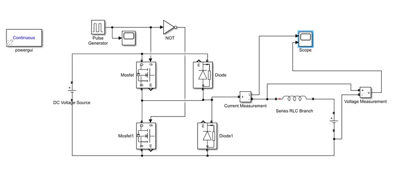
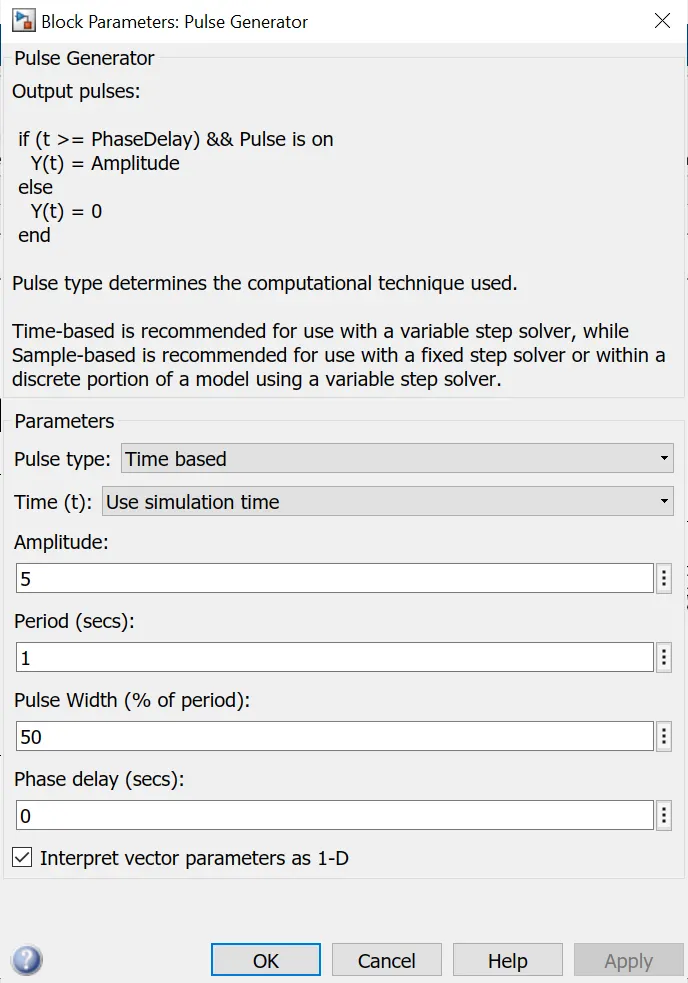
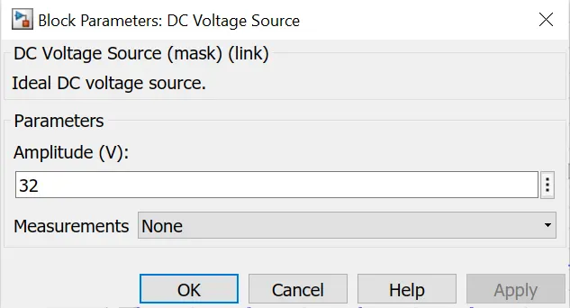
Here in the simulink model of a 2 quadrant chopper the input dc voltage is given as 36V, Pulse amplitude is given as 5, period as 1 sec and pulse width is provided as 50%. The load side dc voltage source is assigned to 16V. A NOT gate is used in the model so that 2 MOSFETS wont get closed at the same time, each time one will be on and the other will be off.
OUTPUT:
Observation:
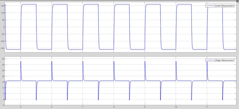
The above result shows the voltage and current waveform in which average voltage is always positive and load current value can be both positive and negetive. When mosfet 1 is on current flow from source to load and the inductor stores energy. When mosfet 1 is off freewheeling diode starts conducting and current direction gets reversed due to inductor discharging. When mosfet 2 is on the load current will be negetive and regenerative braking takes place.
https://drive.google.com/file/d/14HCQ_2UnpElzF1GhK7oMSBvC_tE7dgir/view?usp=sharing
3. Explain in a brief about operation of BLDC motor.
A: BLDC stands for brushless direct current motor.
- They doesnot have brushes
- They are electronically commutated
- Requires a power converter
- Rotor magnetic fields are fixed permanent magnets
- Requires an inverter circuit
- Requires 3 phase
- 2 types of arrangement in BLDC motor are trapezoidal and sinusoidal arrangement
- Hall sensors are present for each phase
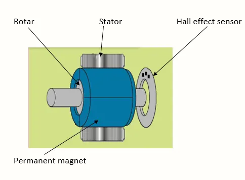
For Brushless DC motor drives its construction implements 2 or more permenant magnets at the rotor to generate a dc magnetic field. It consists of a stator core made up of thin, stacked laminations. It uses an inverter for current control as the current direction has to be changed repeatedly to maintain a constant torque.
Hall sensor provides the information to synchronize stator armature excitation with rotor position. Since the commutation of BLDC motor is controlled electronically, the stator windings should be energized in sequence in order to rotate the motor. Before energizing a particular stator winding, acknowledgment of rotor position is necessary. So the Hall Effect sensor embedded in stator senses the rotor position.
Most BLDC motors incorporate three Hall sensors which are embedded into the stator. Each sensor generates Low and High signals whenever the rotor poles pass near to it. The exact commutation sequence to the stator winding can be determined based on the combination of these three sensor’s response.
BLDC motor require permanent magnets and cannot vary thier magnetic field strength. The permenant magnets used are expensive. But less rotor heat is produced and rotor cooling is easier. As the size of brushless dc drive increases the losses also increases and efficiency decreases. BLDC can operate at unity powerfactor 1 which makes it more efficient in performance.
OPERATION:
BLDC motor works on the principle similar to that of a conventional DC motor, i.e., the Lorentz force law which states that whenever a current carrying conductor placed in a magnetic field it experiences a force. As a consequence of reaction force, the magnet will experience an equal and opposite force. In the BLDC motor, the current carrying conductor is stationary and the permanent magnet is moving.
When the stator coils get a supply from source, it becomes electromagnet and starts producing the uniform field in the air gap. Though the source of supply is DC, switching makes to generate an AC voltage waveform with trapezoidal shape. Due to the force of interaction between electromagnet stator and permanent magnet rotor, the rotor continues to rotate.
With the switching of windings as High and Low signals, corresponding winding energized as North and South poles. The permanent magnet rotor with North and South poles align with stator poles which causes the motor to rotate.
Advantages:
- Less overall maintenance due to absence of brushes
- Reduced size with far superior thermal characteristics
- Higher speed range and lower electric noise generation.
- It has no mechanical commutator and associated problems
- High efficiency and high output power to size ratio due to the use of permanent magnet rotor
- High speed of operation even in loaded and unloaded conditions due to the absence of brushes that limits the speed
- Smaller motor geometry and lighter in weight than both brushed type DC and induction AC motors.
- Long life as no inspection and maintenance is required for commutator system
- Higher dynamic response due to low inertia and carrying windings in the stator
- Less electromagnetic interference
- Low noise due to absence of brushes
Disadvantages:
- These motors are costly
- Electronic controller required control this motor is expensive
- Requires complex drive circuitry
- Need of additional sensors
Application:
Brushless DC motors (BLDC) use for a wide variety of application requirements such as varying loads, constant loads and positioning applications in the fields of industrial control, automotive, aviation, automation systems, health care equipments etc.
- Computer hard drives and DVD/CD players
- Electric vehicles, hybrid vehicles, and electric bicycles
- Industrial robots, CNC machine tools, and simple belt driven systems
- Washing machines, compressors and dryers
- Fans, pumps and blowers
REFERENCE:
Mathworks
Google images
Wikipedia