Week-7 Challenge: DC Motor Control
Aim :
1 A. Explain a MATLAB demo model named ‘Speed control of a DC motor using BJT H-bridge’.
B. Comment on the armature current shoot-up from the scope results.
C. Refer to the help section of ‘The Four-Quadrant Chopper DC Drive (DC7) block’. Compare it with the H-bridge model.
2. Develop a 2-quadrant chopper using simulink & explain the working of the same with the relevant results.
3. Explain in a brief about operation of BLDC motor.
Objective 1:
A.
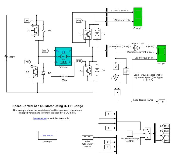
Above model is the speed control of DC motor using BJT H bridge.
Model consist of pulse generator, BJT H-Bridge,Speed and Torqe Calculator and also the DC motor model.
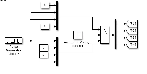
Above pulse generator model has frequency of 500 Hz. It has armature voltage control with the threshold value of 0.5 that means it gives input to the H bridge as 50% duty cycle. That means for 1 second of time cycle the bridge will be set on for 0.5 sec only and off for other 0.5sec.
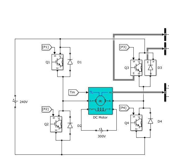
Next is the motor and H-bridge model.
Motor model is existing model in simulink . Motor specifications are as follows:
Speed - 1750 rpm
Power - 5HP
V- 240 volt
and Field Voltage - 300v
H- Bridge is as shown where all four terminals connected to one positive and one negative.
H-bridge will function in a such way that at atime there will be only one path for the current to follow,
Ex. If terminal one is opened at that time terminal four will open and will create path for the current in second cyle terminal 3 and 2 will open and create path for the current and with this machine will be operated.
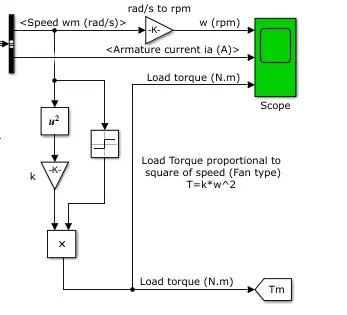
Above block is for the measurement of the speed and velocity generated by the motor and is shown in graphical format with the help of scope.
This H-bridge BJT model has simulation time of one second by default.
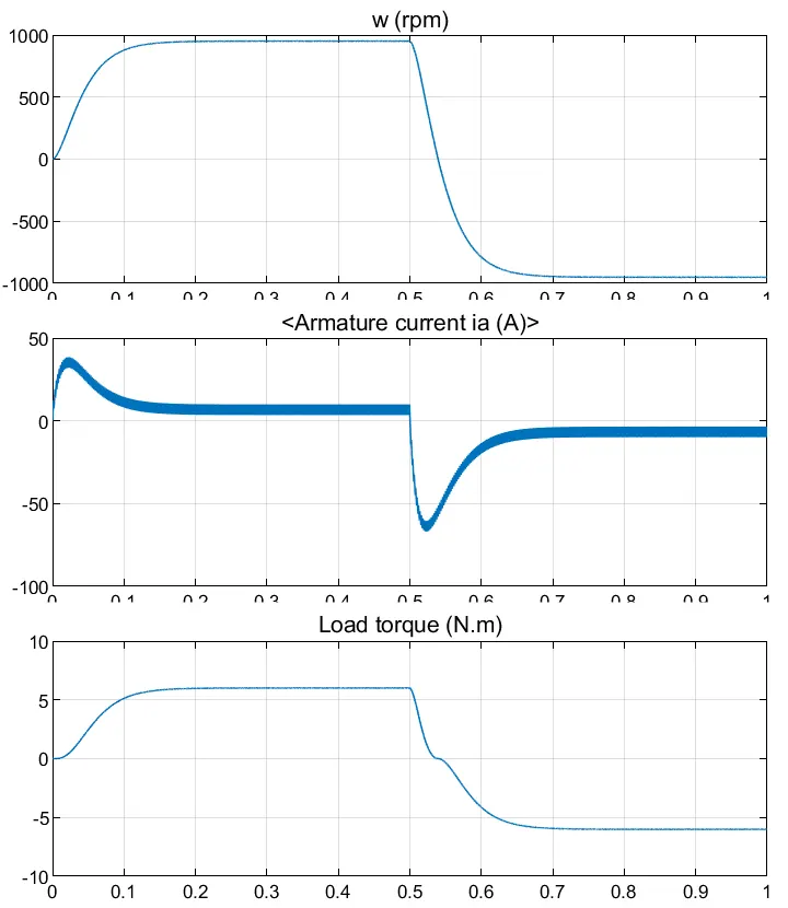
we can see the result of torque, current and angular velocity.
This simulink model is only made for 1 sec cycle after 1 second simulation it will not show related results until some modifications are done.
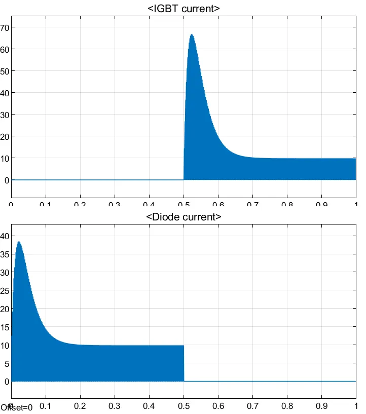
This is the current shoot in IGBT and diode.
B.
Current shoot in the IGBT is shown after the half cycle of the controller and also curretnvalue for both of them is quite different.
Objective 2:
Objective 3:
Brushless DC motor.
Construction:
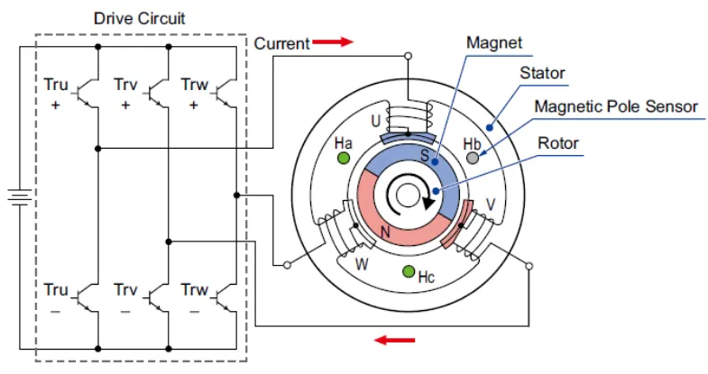
Brushless DC motor consists of Permanant Magnet ,Rotor and Stator with winding ana one magnetic pole sensor to detect the poles of the stator.
Rotor - Rotor is attached to permanant magnet and placed in middle or center of the motor, It is rotating part of the motor,
Stator - Stator is fixed part of the motor surrounding the rotor which carries the iron rod or steel rod with copper winding.
Magnetic pole sensor - Magnetic pole sensor is to detect the poles of stator and according to control the current in motor.
Working of the Brushless DC motor.
Principle.
Brushless DC motor works on the principle of current carrying conductor placed in magnetic field experience a force.
When current flows through a winding of stator it induces the magnetic field in the stator and acts as pole depending upon the direction of current magnet stator changes the poles.
But how it changes the pole?
Pole sensor will detect the pole of the rotor and send the signal to the control as per that controller changes the current direction in coil
In the case of 3-Phase motor there are three pole generation windings, each time pole sensor detects the pole of permanant magnet it will send the signal to controller and controller will change the direction of the current for that winding only.
Advantages
1. Brushless DC motor is modified version of brushed motor so the friction due to abscense of brushes is less and hence the life of the motor increases.
2. In 3 phase it is easier to get the stable speed and torque.
3.Due to negligible losses the power factor is almos unit.
Conclusion-
Objective 1 and 3 achieved.