Replication of Aston Martin ONE-77 with Avanced Surfacing in SOLIDWORKS
Objectives-
- To learn Advance Surface modelling in solidworks.
- To learn how to create sketches and curves required to create complex surfaces for body.
- To learn how to use varies surfacing, modelling and assembly tools and features in solidworks.
Introduction-
Solidworks is a multi-platform Computer-aided design (CAD), Computer-aided engineering (CAM) Computer-aided Engineering (CAE) and Analysis software developed by a French Company Dassault Systemes. Solidworks CAD modelling software is used in the following industries: Aerospace & Defence, Architecture, Engineering and Construction, Consumer goods - distribution, FMCG - Distribution, Energy, and processes, Finance and Corporate Services, High Technology, Industrial Equipment, Life Sciences, Marine & Offshore, Natural Resources, and Transport & mobility. Solidworks enables the creation of 3D parts from 2D sketches surfacing, sheet metal, weldments, moulded tooling parts up to the definition of mechanical assemblies.
In solidworks part modelling design engineer can design part model using different design tools and features. In part modelling there are various types 3D modelling, surfacing, sheet metal, weldments.
Then there is solidworks assembly where we can assemble different part models in single body with proper mating constraints.
Nowadays industries are working for attractive. good looking, good ergonomically design aesthetical Product. To design such kind of attractive product designer should have knowledge of surface modelling, surface model has three dimensional geometric properties unlike solid model, surface modelling can help designer to design casting components, injection moulding plastic components, mould designs and many others engineering products. Solidworks surface modelling feature have number of surface modelling tool to create complex 3D surface model.
Some of the 3D modelling features are discussed below
Sketch – Sketch feature used to draft 2d sketch of the required 3D model. Sketch feature contains a different tools such as line, spline, circle, rectangle, fillet, ellipse, fillet, chamfer, Text, convert entities, Offset entities, move, copy, Pattern etc.
Features Manager – It is used convert the 2D sketch into 3D modelling. It contains features like Extrude boss, revolve boss, swept boss, Lofted Boss all this features are for both adding the material as well as removing the material. Also there is chamfer, fillet, mirror, rib, shell, dome etc for 3D objects specifically
Surfacing – Solidwork also has surfacing workbench which is used to create 3D surface. It contains extrude, filled, swept, lofted, boundary, fillet, extend etc for adding the material while to remove the surface there is option trim surfaces.
In this project I have learnt about how to create surface model for the Aston Martin One-77 step by step with the help of surfacing tools used in solidworks with this project I have familiarized with the different surfacing tools used during creation of the surface models. While for the Tire, Rim, Breaks etc requires 3D solid modelling.
Flow of Project-
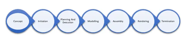
Design-
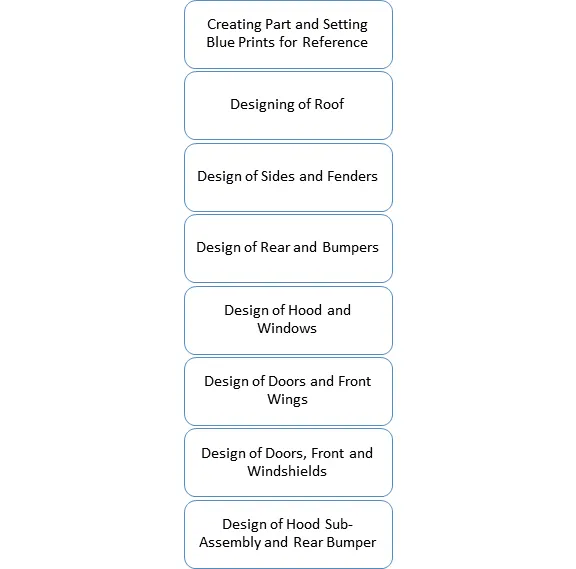
It is hard to design the such complex geometry and surfaces in one go. That’s why we separated geometry in simple and different parts. First we created single parts separately and then add or attach them together to form single and whole surface model. After the surface modelling we created 3D solid models for the necessary parts, then finally we assembled all the parts together to create the final model.
Surface Model Design of the Aston Martin One -77 as below
Solid Model Design of Aston Martin One-77
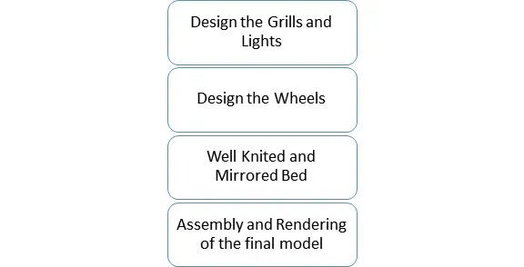
Let us go in detail of the every step:
- Creating Part and Setting Blue Prints –
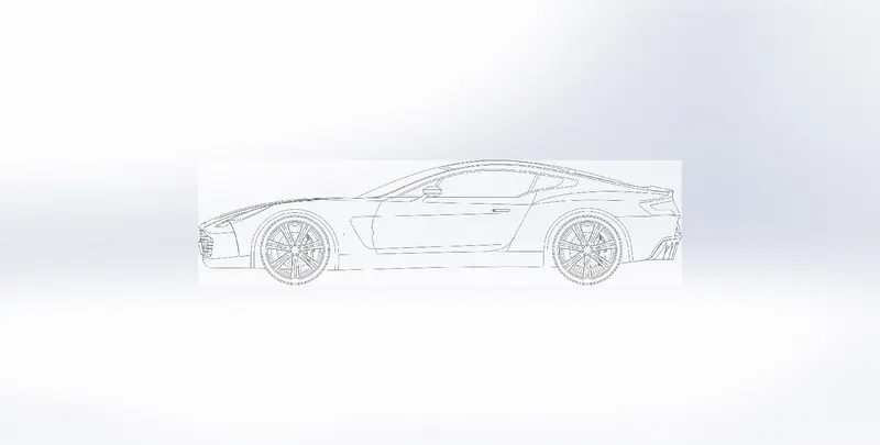
Blueprints
First of all we started with creating part in solidworks with setting dimensions and units in CGS system. Then setting the blueprints onto their respective plane with appropriate dimensions and well transparency to draw the sketches with that references.
We used sketch picture tool under sketch tools it is useful from which we can trace the dimensions and curves as per the curves of the blue prints and get to accuracy of the curves.
Surface Modelling – We used different solidworks tools in surface modelling. It contains various Sketch tools, Features tools and Surface tools
Tools Used in Surface Modelling –
- Sketch Tools –
- Spline – It is tools used to create the curved lines. Spline tool can create the infinite numbers of point.
- Line – Line tool is used to create the straight lines also we can create number of connected lines with this tool.
- Projected Curve(under the features Curve) -This Feature tool is used to create the projected curves. There are two parts in projected curve that are;
1.Sketch on Sketch – This tool requires two different sketch to create the projected curve. The curve will always be created where two sketch intersect each other in 3D.
2.Sketch on Face – This tool requires a sketch and face on which it will produced. When appropriate face and sketch is selected the curve will be produced on that respective face.
- Extrude Surface – A extrude surface is produced from single sketch. Even single line can be extrude as surface with this command.
- Swept surface – Swept surface can be produced with the single profile and one direction sketch with this we can create the surface any of the profile as per requirement.
- Boundary Surface – Boundary surface feature can be operated under more than one sketch and edges which acts as the boundary or enclosure for the certain profile or face. Boundary surface acts in two directions. Sketches and edges for the enclosure of faces and profile required to be selected in particular way to achieve that surface. Also the sketches and edges need to be in continuity. Surface can be provided with the tangency and curvature with respect to nearby surfaces
- Filled Surface – This feature can be operate with multiple sketches and edges. It will fill the selected sketches and edges with surface. This surface can be provided with tangency and curvature with respect surrounding surfaces.
- Offset Surface – offset surface is used to create the offset from the surface. Also can create offset surface with zero distance.
- Ruled Surface- The Ruled Surface creates surfaces that extend out in a specified direction from selected edges. Examples of how we can use ruled surfaces:
A] Add tangent extensions to complex surfaces
B] Create drafted sidewalls
C] Replace non-drafted surfaces on imported models with drafted surfaces (using the Tapered or Sweep type)
D] Create parting and interlock
- Fillet - A fillet is a tool is used to create the smooth rounded surfaces with certain radius out of the sharp edges along the bodies. we can fillet all edges of a face, selected sets of faces, selected edges, or edge loops. There are four types of fillet i.e.
Fillet Type - constant type fillet, variable size fillet, face fillet, and full round fillet.
- Delete Face - This tool used to delete certain selected surfaces or faces from the body. Delete face deletes the face and automatically generate certain face or can trim and patch other respective surfaces.
- Delete/ Keep Body – This tool is used to deleting and keeping body in such a way that deleting a body will not create any geometrical distortions and errors.
- Extend Surface - Extend a Surface is a tool using which we can extend a surface by selecting an edge, multiple edges, or a face.
- Trim Surface - The trim Surface tool is used to trim the intersecting surfaces. We can use a surface, plane, or sketch as a trim tool to trim intersecting surfaces. We can also use a surface in conjunction with additional surfaces, Property Manager, under Trim Type, there are two types available, Standard and Mutual.
Standard - Trims surfaces using surfaces, sketch entities, curves, planes etc
Mutual – By selecting the multiple surfaces we can trim the surfaces.
- Knit Surface - The Knit Surface tool is used to combine two or more faces and surfaces into one. As the word suggests it works as sewing machine to different surfaces.
- Surface Loft - Lofted surface is to join the two different profile into single surface and create transition between them with guiding curves. It is very beneficial in the surfaces with different profiles which are difficult to produce with simple extrude surface.
- Cut with Surface – Cut with surface tool is used to cut the solid profiles with respect to selected surface which can be used to remove the undesirable parts.
We used above tools and created different car bodies as surface model, and the result are as follows-
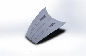
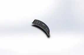
Hood Rear Bumper
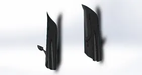
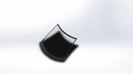
Doors Window
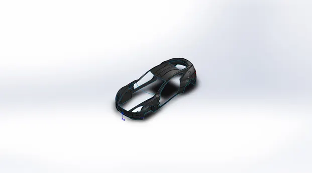
Main Body OF the Aston Martin
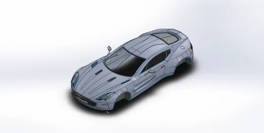
Well Knited Body with All the Surfaces
Solid Modelling – We used different solid modelling tools in the solidworks to produce the necessary solid models
- Extruded Boss/Base – It is used to create the solid models from the sketched profiles and this tool requires closed contours to created the solid model out of sketch. For non closed contours it will activate thin feature. This feature is also available with cut option which removes the material from the selected body of the size of profile.
- Revolved Boss/Base – It is used to create the revolved body from the selected feature.This feature requires the sketch and the axis of revolution for the body. This feature also comes with the cut operation which removes the material in revolved direction from the selected bodies.
- Fillet – Fillet tool is used to convert the sharp edges of solid bodies or surfaces into smooth curves with given radius of particular size which will not distort geometry.
- Combine – Combine tool is used to combine all the solid bodies into single part but for some bodies it will not combine such as common bodies and patterns.
- Chamfer – Chamfer tool is used to create sharp edges to slant edges with some angle and distance
- Swept Boss/Base – Sweep boss is used to create the profile in certain direction for which we have to provide with the profile and directional sketch. Also comes with the cut operation in which it works the same but removes the material from the selected profile.
- Lofted Boss/Base - Lofted Boss is to join the two different profile into single model and create transition between them with guiding curves. It is very beneficial in the Modelling with different profiles which are difficult to produce with simple extrude Boss.
- Delete/ Keep Body – This tool is used to deleting and keeping body in such a way that deleting a body will not create any geometrical distortions and errors.
- Mirror – Mirror is to create the exact replica as in the mirror. By selecting the mirror to be bodies and the plane of the mirror. It will also merge solids and knit the surfaces.
- Pattern – Pattern are used to create the or repeat some kind of modelling operation or solid model in sequential manner
There are different kind of patterns 1.Linear 2. Circular 3. Curve Driven etc
Result for the use of above tools in this project is as follows.
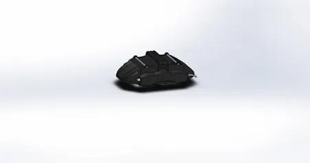
Caliper
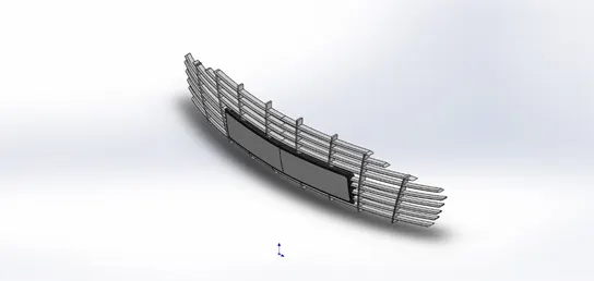
Front Grills
Assembly of the Model
Assembly is a file consisting of two or more parts and other assemblies called sub-assemblies. Adding a component to an assembly creates a link between the assembly and the component. Changes in the component are automatically reflected in the assembly
- Sub-Assembly - When an assembly is a component of another assembly, it is referred to as a subassembly. We can nest subassemblies in multiple levels, to reflect the hierarchy of we design. In this project's assembly, we have different parts like doors, hood, windows, bumper, etc. and sub-assemblies of front and rear wheels. All the parts of the car are assembled together with the help of the mate feature.
- Add components -When we place a component (either an individual part or a subassembly) in an assembly, the component file is linked to the assembly file. The component appears in the assembly, the component data remains in the source component file. Any changes we make to the component file update the assembly
- Edit Assembly components - From an assembly, we can open a component in a separate window to make changes. When we switch back to the assembly window. we rebuild the assembly to incorporate the changes.
- Mate - Mates create geometric relationships between assembly components. As we add mates, we define the allowable directions of linear or rotational motion of the components. We can move a component within its degrees of freedom, visualizing the assembly's behaviour.
From Assembling the individual component we get the following result-
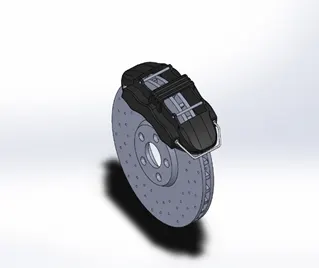
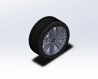
Breakes Wheel
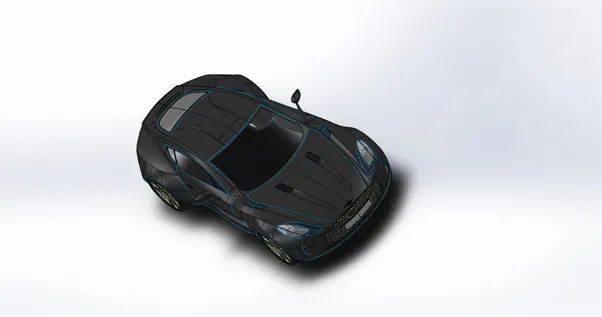
Isometric View of the Final Body
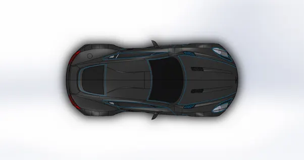
TOP View of the Final Body
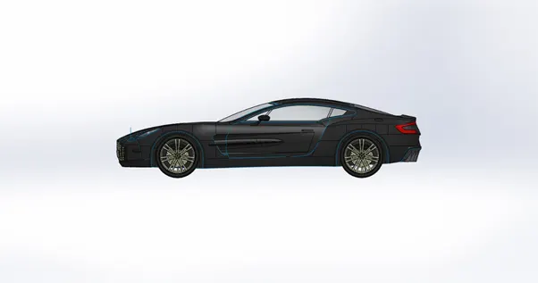
Side View of the Final Body
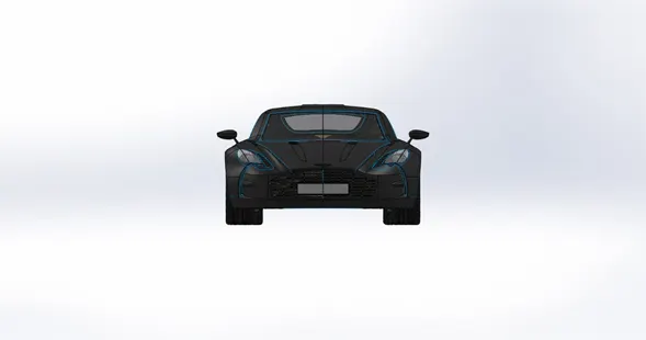
Front View of the Final Body
Rendering-
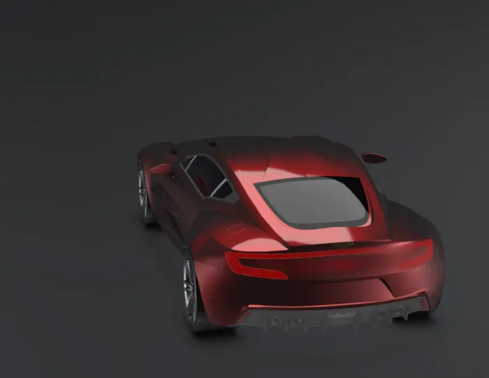
Rendering is one of the most important tool in the solidworks. Solid models and surface models created in solidworks are shown with unecessary edges and lines on the surface as well as the it shows where the places have been knitted and joined. Using render option it will hide all the unecessary details and lines in the model.
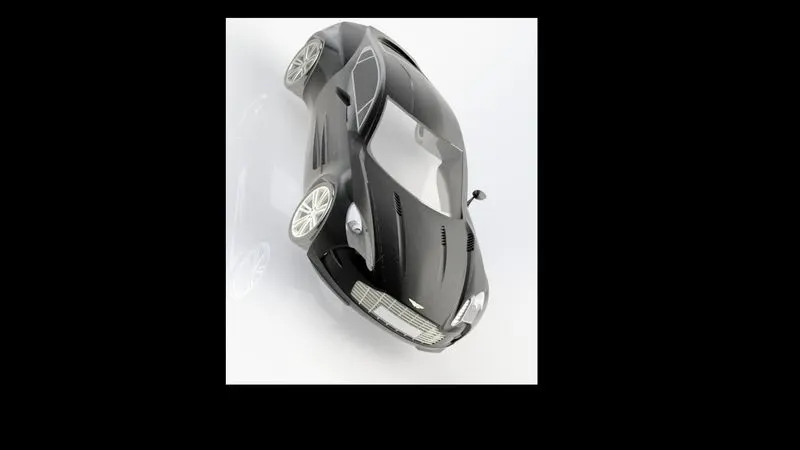
Rendering with photo view 360
Rendering With Solidworks Visualize-
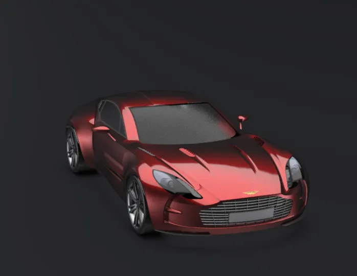
Results And Conclusion
We completed all three objectives of the project.
- We were able to use the surfacing, sketching, solid modelling and assembly tools.
- We were able to do renderings and final finishing touch of the body.
- We were able to achieve the final result that is the well knitted and assembled body of the Aston Martin One-77 with rendering.