Simulink Models for the doorbell and Automatic Fan
Objective-
1.Make a Simulink model of Doorbell using solenoid block.
2.Use a thermistor to sense the temperature of a heater & turn on or turn off the fan as per conditions.
Simulink Models-
1.Door Bell Model-
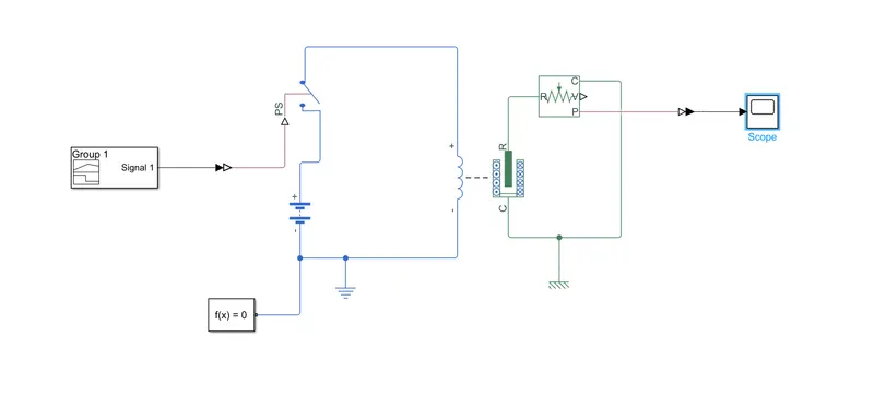
Blocks Used-
1.Solenoid - It is mechanical block in library with actual replication of solenoid.
2.Signal Builder - It is simulink library which is used to create a physical signal as per requirement
3. Switch(Physical signal as threshold)-This switch is closed when the signal value is greater than threshold value.
4.Power source(Battery) - It is typical battery which acts as source.
5.Ideal Translational Motion sensor - It is mechanical block used to detect the translational motion, In this we used it to detect the motion of plunger.
6.Electrical Reference (Ground) - Typical ground used in electrical systems.
7.Mechanical Translational Reference - Reference for translational motion.
Results when different parameters are set.
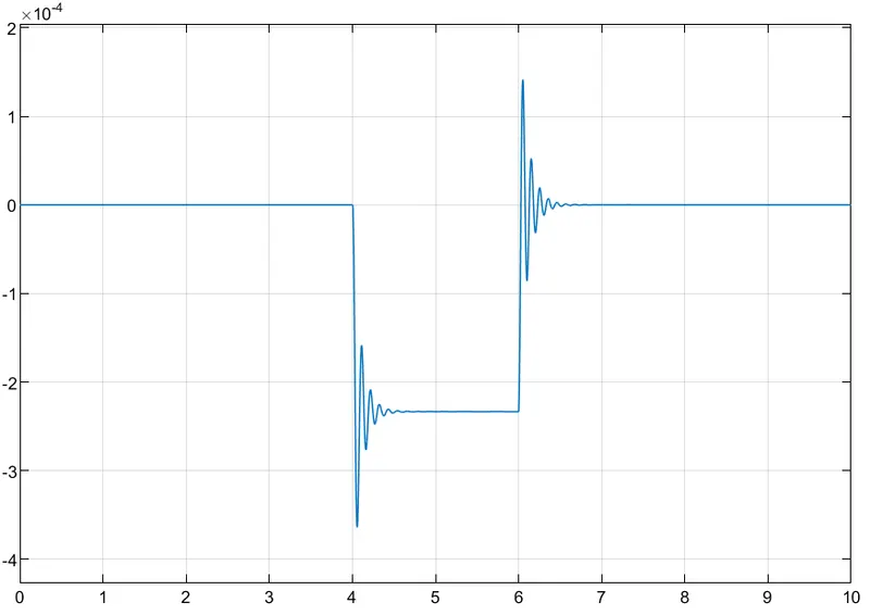
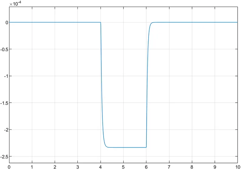
1.With the help of signal builder we create the signal with amplitude 1 for time 4-6 seconds only and given it to the physical signal switch with threshold of 0.5 which means whenever the signal is more than 0.5 circuit will be closed.
2. First we set the dampin value as 1 which is default for the block.result is as follows
Damping value set to 1-
3. We set the the damping value to 10 and the result are as follows.
Dampin value set to 10-
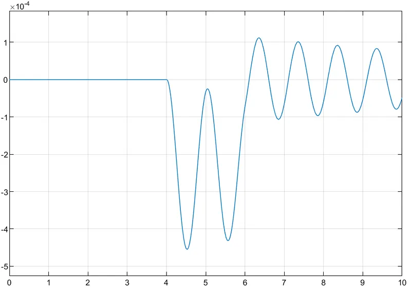
Now we are keeping the damping value as 1 and changing the mass to 5 kg as damping value is not sufficient to damp 5 kg mass object it will come at rest after saveral oscillations
Damping value 1 and mass 5 kg
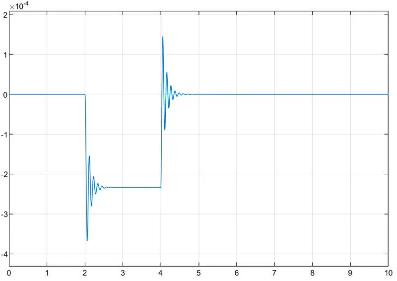
Now we set the builder signal to 1 in time range of 2-4 seconds and keeping solenoid block values default.and hence the result are as follows.
Signal set between 2-4 second with damper 1 and mass 0.05kg-
2 - Turning Fan ON and OFF as per given conditions
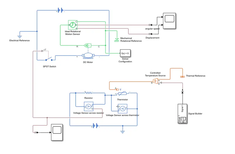
Blocks Used
1. Thermistor - This Block acts as typical thermistor which changes resistance according to the changing temperature.
2. Battery(Power Source) - Similar to typical battery acts as power source.
3.Voltage Sensor - This block is used to sense the value of the voltage across resistor.
4. resistor - Acts as typical resistor in electrical system we can change the value of resistance.
5. Signal Builder - Is used to build simulink signal.
6.Controlled temperature Source- Controlled temperature source acts as temperature source but we can controll the temperature values by connecting external physical signals.
7.Thermal Reference- Typical thermal block acts as thermal reference.
8. Electrical reference - Typical electrical ground connection.
9.Mechanical Rotational reference- Typical rotational reference
10. Ideal Rotational Sensor - It is used to sense the rotational motion of the object.
11.DC motor- It is block acts as typical DC motor.
12, SPST Switch- SPST switch acts on threshold voltage value, means when voltage is greater than threshold then switch is closed otherwise its open
13. Solver Configuration -provides the solver for the system.
14.Scope - It is used to visualize the connected qualtities against time.
Conditions For the above simulink blocks are as follows.
Temperature source: 20 °C from 0 to 10 seconds, 27 °C from 10 to 30 seconds, 23 °C from 30 to 50 seconds
Fan conditions: ON if the temperature above 25 °C, OFF otherwise
1. According to conditions we built the signal in kelvin. 298.15 is 25celcius ,300 is 27 celsius, 293 is 20 celsius and 296 is 23 celsius.
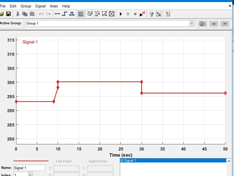
2. We ran simulation once we found the voaltage value across resistor when the temperature is 298.15k, we kept this as the threshold value for switch and again ran the system.
3. We are getting the following result when we are keeping the default values for DC motor.
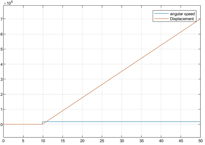
4. After setting the value for damping it working correctly, as you can see at the value of voltage at 25 celsius fan is turning on. and when at 30 sec the value is less than threshold we are again getting the fan is turned of.
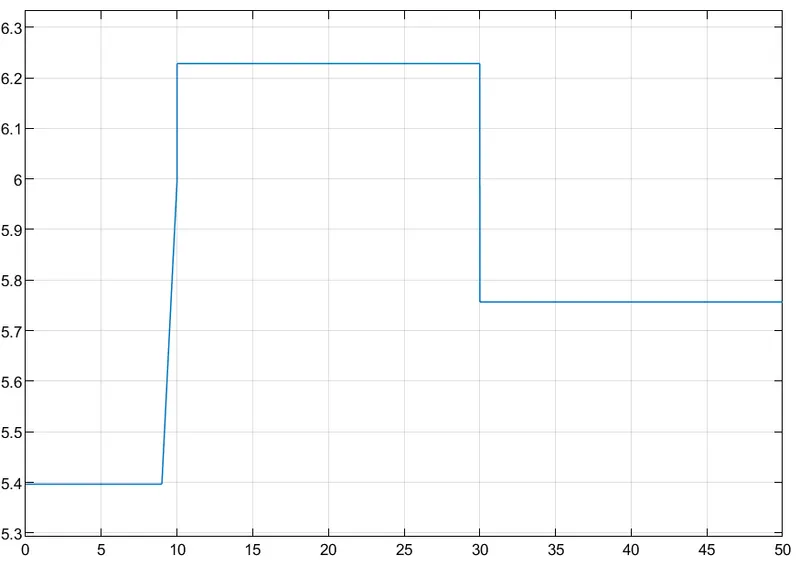
as you can see in above graph value of the voltage at the 25 celsius is approximately 6.
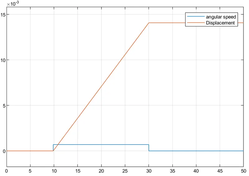
we can directly connect the voltage value accross thermistor but the value is almost negative that's why we are using another connection.
Conclusion -
We were sucessfully able to create simulink models for both the systems and able to generate the results.