Week-7 Challenge: DC Motor Control
1.
A.
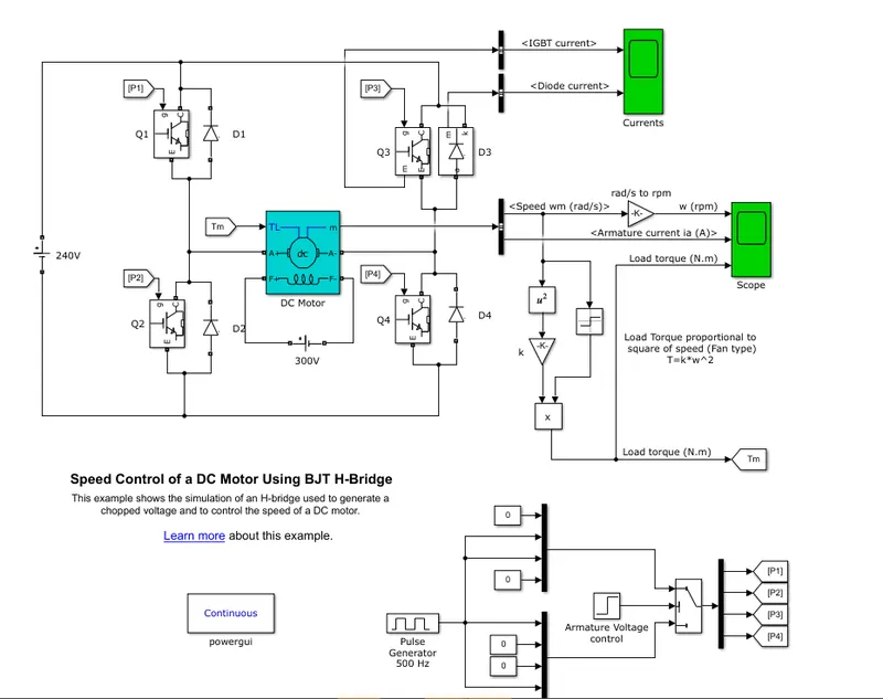
The H-bridge consists of four BJT/Diode pairs . Two transistors are switched simultaneously- Q1 and Q4 or Q2 and Q3. When Q1 and Q4 are on, a positive voltage is applied to the motor and diodes D2-D3 operate as free-wheeling diodes when Q1 and Q4 are switched off. When Q2 and Q3 are on, a negative voltage is applied to the motor and diodes D1-D4 operate as free-wheeling diodes when Q2 and Q3 are switched off. Here the BJTs are simulated by IGBT models. A 5HP 24V 1750 rpm motor is used here. It simulates a fan type load. Load torque is proportional to square of speed. Armature mean voltage can be varied from 0 to 240V by variying the pulse duty cycle from 0 to 100%.
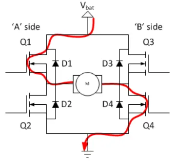
Current flow when Q1 and Q4 is on
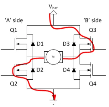
Current flow when Q2 and Q3 is on
Simulation results
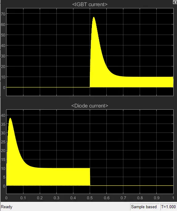
From the above graph we can find that 0-0.5 sec the current flows through diode D3. and from 0.5-1 sec the current flows through Q3. The motor starts with 75%dutycycle which is equal to 75 % of 240 =180V. Initially the motor runs in positive direction 0-0.5sec then suddenly reverse its direction.
Motor speed, Armature current, Load torque plots
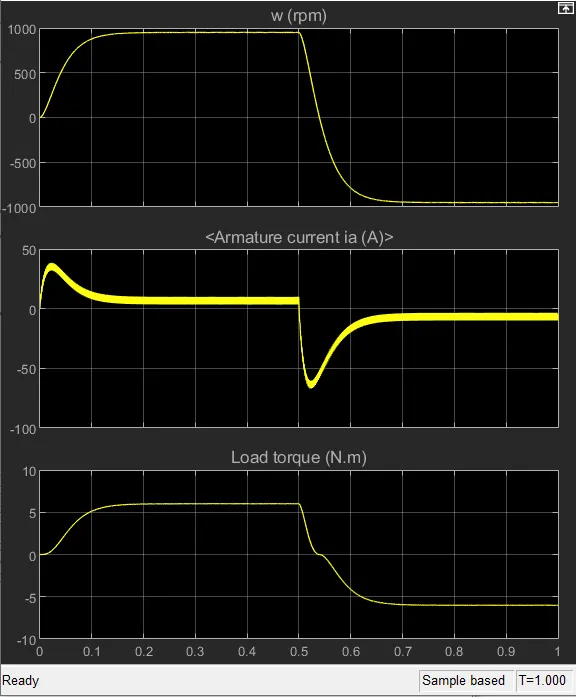
From armature current graph we can see that at starting there is a sudden increase in current at 0 sec and also seen in 0.5 sec when switching occurs. As the voltage gets changed the speed of the motor also changing. In switching the direction of current we can see a surge in current due to transient switching. As already a current flowing in the circuit when we change direction the current in the circuit adds to the changed direction of current this phenomenon is observed as a surge in 0.5 sec.
B).
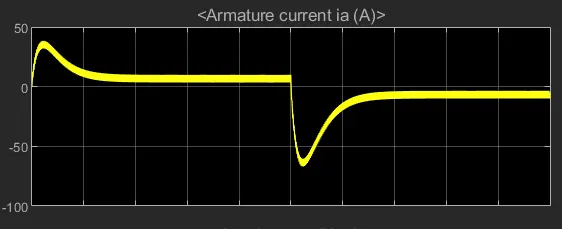
From armature current graph there is a sudden increase in current at 0 sec. and at 0.5 sec- when the direction changes to negative. This is due to the transient switching occuring in the circuit. at 0.5 sec there is a huge surge. As already a current flowing in the circuit when we change direction the current in the circuit adds to the changed direction of current this phenomenon is observed as a surge in 0.5 sec.
The surge can be minimized by reducing the duty cycle.
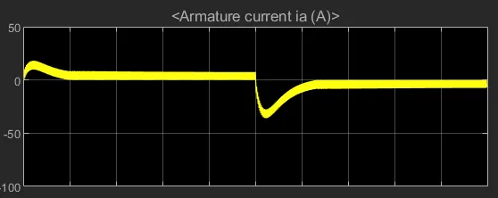
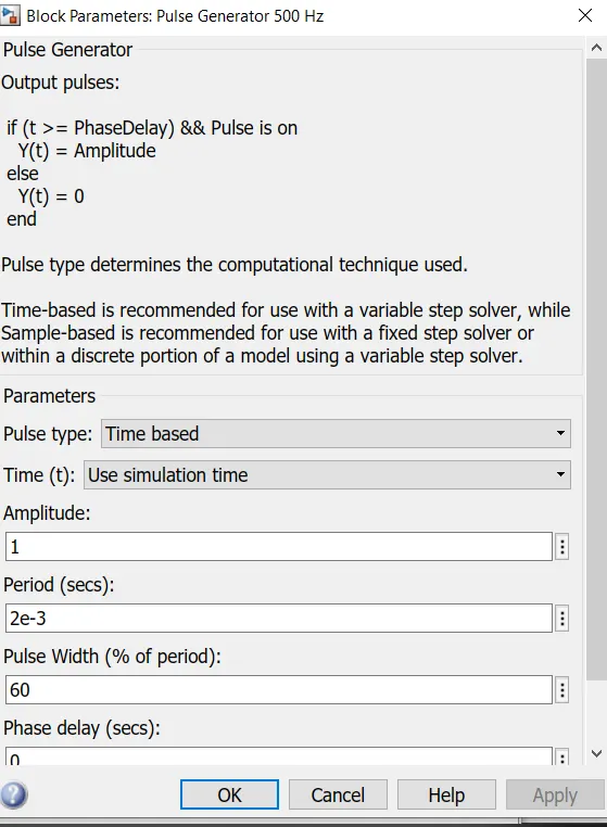
This plot showing armature current at 60% duty cycle.
C.
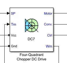
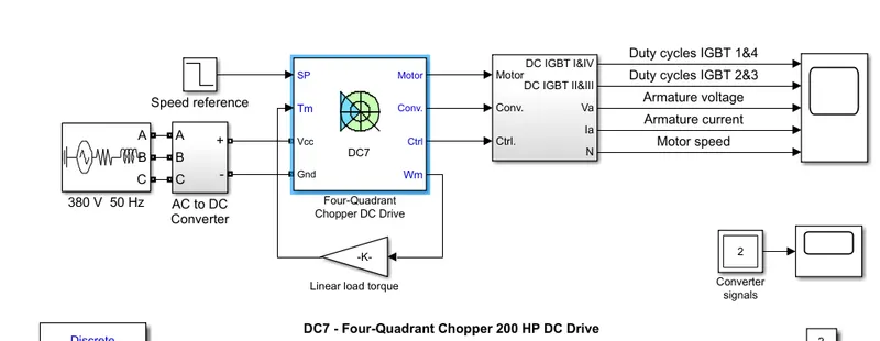
This is an example of four quadrant DC7 block drive.
DC7 is a four quadrant dc supplied chopper . It has a closed loop speed control also. Speed control loop outputs the reference armature current of the machine. It uses the PI controller. Chopper duty cycle corresponds to the commanded armature current. is derived. This duty cycle is compared with a sawtooth carrier signal to obtain the required PWM signals for the chopper.
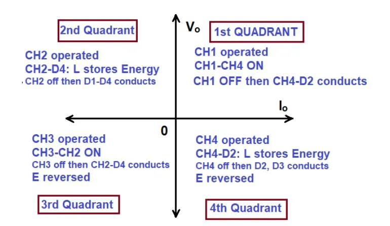
Four quadrant operation
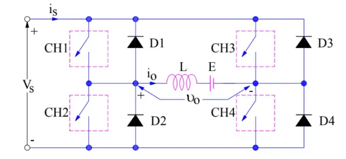
CH1,CH2,CH3,CH4 are switches and D1,D2,D3,D4 are diodes
the four quadrant operation can be represeted like
2.
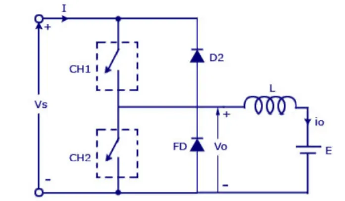
Circuit diagram of two quadrant chopper
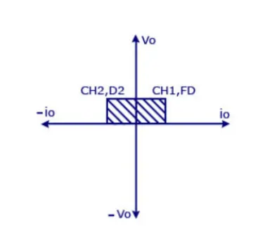
Two quadrant operation.
Two quadrant chopper is called as type C chopper. We will always get a +ve voltage output as the freewheeling diode is present across the load. When the chopper is on the free wheeling diode starts conducting and the output voltage V0=Vs. The direction of i0 will be reversed .i0 will be flowing towards the source and it will be positive regardless of the chopper is on or the FD conducts. The load current will be negative is the chopper is off or the D2 conducts. average voltage will be always positive. But the average current might be positive or negative. For regenerative breaking and motoring these type choppers used.
Simulink model
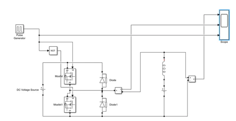
Scope results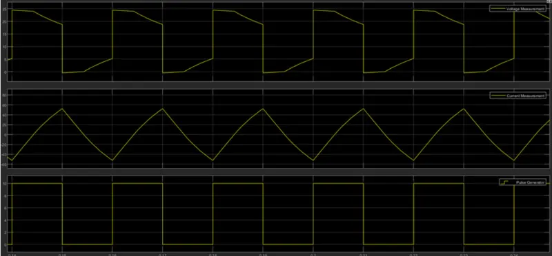
Output voltage is positive value only while current changes to negative value also.
3.
BLDC Motor
BLDC-Brush Less D C motor is electrically commutated motor. Normal brush type dc motors are mechanically commutated. Normal dc motors has inner rotor which contains the winding. outer stator has permanent magnet. In BLDC outer portion is rotating, ie: permanent magnet is rotating. Inner part is stator. Which contains the winding. Inner coils are switched electronically by transistors at certain rotor position which is determined by using hall sensors. BLDC motors are very efficient. its efficiency in the range of 85-90%, while normal brush type dc motor efficiency falls between 75-80%.
Inner rotor BLDC is also possible. Main difference is the electrical commutation.
Operation
In BLDC the magnetic field generated is varied based on the rotor/shaft position. Rotor or shaft position feed back is obtained using hall sensors. Hall sensors can detect near by magnetic field. For north and South poles hall sensors develop a high and low signals. Based on that feed back near by poles can be generated to oppose the rotor and keep running.
A similar process is shown below
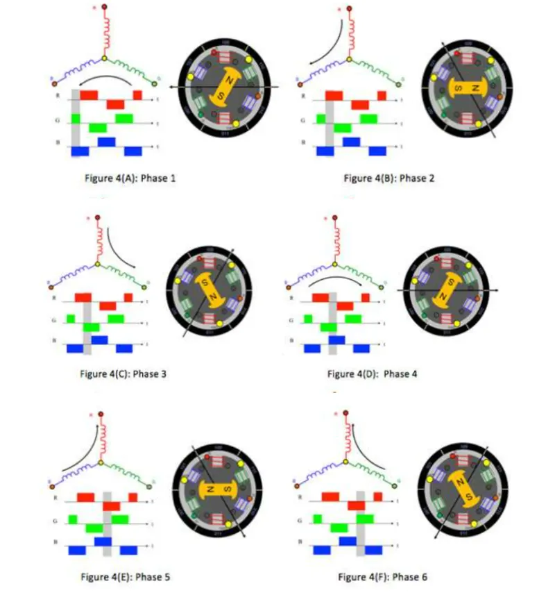
Whenever the poles of rotor comes close to any of the winding. the corresponding winding gets energized in a way that to oppose the rotor
Advantages of BLDC
Less maintenance
reduced size and heat generation.
High speed
Low noise
High efficiency
High output power to size ratio
Light weight
Long life
Higher response
Less Electro magnetic interference
Disadvantages
Costly
Electronic controller required
Complex circuitry
Need of additional sensors
Application
Computer hard drives
Electric vehicle
Robots
CNC Machines
Washing machines
Fans, Blowers