Week-7 Challenge: DC Motor Control
1. A. Explain a MATLAB demo model named ‘Speed control of a DC motor using BJT H-bridge’.
B. Comment on the armature current shoot-up from the scope results.
C. Refer to the help section of ‘The Four-Quadrant Chopper DC Drive (DC7) block’. Compare it with the H-bridge model.
ANS)
A.power_Hbridge MATLAB demo model named ‘Speed control of a DC motor using BJT H-bridge’.
In this model they used many blocks name given below:
DC voltage source, mux, IGBT, pulse generator, bus selector, diode, from, goto, scope, constant, powergui, step for armature voltage control, signum, math function, gain, switch, product.
This example shows the simulation of an H-bridge used to generate a chopped voltage and to control the speed of a DC motor.
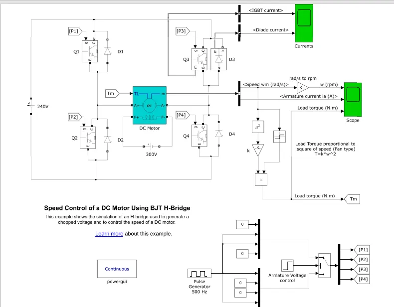
The Bipolar Junction Transistor (BJT) when used for power switching applications, operates as an IGBT. When it is conducting (BJT operating in the saturated region), a forward voltage Vf is developed between collector and emitter (in the range of 1 V). Therefore, the IGBT block can be used to model the BJT device.
The IGBT block does not simulate the gate current controlling the BJT or IGBT. The switch is controlled by a Simulink® signal (1/0). The DC motor uses the preset model (5 HP 24V 1750 rpm). It simulates a fan type load (where Load torque is proportional to the square of speed). The armature mean voltage can be varied from 0 to 240 V when the duty cycle (specified in the Pulse Generator block) is varied from 0 to 100%.
The H-bridge consists of four BJT/Diode pairs (BJT simulated by IGBT models). Two transistors are switched simultaneously: Q1 and Q4 or Q2 and Q3. When Q1 and Q4 are fired, a positive voltage is applied to the motor, and diodes D2-D3 operate as free-wheeling diodes when Q1 and Q4 are switched off. When Q2 and Q3 are fired, a negative voltage is applied to the motor, and diodes D1-D4 operate as free-wheeling diodes when Q2 and Q3 are switched off.
The motor starts in the positive direction with a duty cycle of 75% (mean DC voltage of 180V). At t= 0.5 sec., the armature voltage is suddenly reversed and the motor runs in the negative direction.
'Scope' shows motor speed, armature current, and load torque and 'Currents' shows currents flowing in BJT Q3 and diode D3.
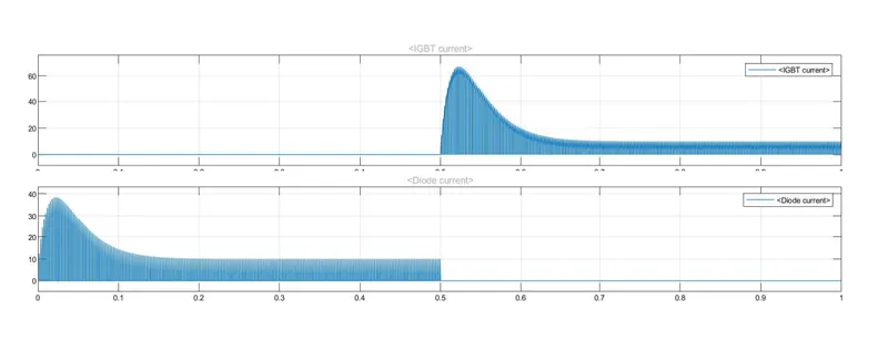
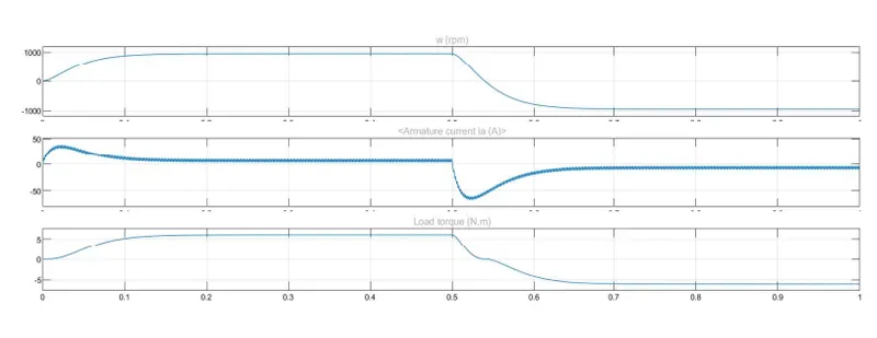
B.armature current shoot-up from the scope result:
so armature current will increase for some small-time and then decreases but not equal to 0 and remain constant for half time. Then goes to negative direction with a decrease of omega and torque.
C. Refer to the help section of ‘The Four-Quadrant Chopper DC Drive (DC7) block’. Compare it with the H-bridge model.
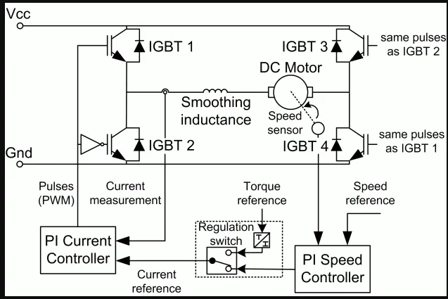
The Four-Quadrant Chopper DC Drive (DC7) block:
The Four-Quadrant Chopper DC Drive (DC7) block represents a four-quadrant, DC-supplied, chopper (or DC-DC PWM converter) drive for DC motors. This drive features closed-loop speed control with a four-quadrant operation. The speed control loop outputs the reference armature current of the machine. Using a PI current controller, the chopper duty cycle corresponding to the commanded armature current is derived. This duty cycle is then compared with a sawtooth carrier signal to obtain the required PWM signals for the chopper.
The main advantage of this drive, compared with other DC drives, is that it can operate in all four quadrants (forward motoring, reverse regeneration, reverse motoring, and forward regeneration). In addition, due to the use of high switching frequency DC-DC converters, a lower armature current ripple (compared with thyristor-based DC drives) is obtained. However, four switching devices are required, which increases the complexity of the drive system.
H-bridge:
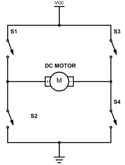
H bridges are available as integrated circuits or can be built from discrete components. The term H bridge is derived from the typical graphical representation of such a circuit. An H bridge is built with four switches (solid-state or mechanical).
An H-bridge circuit can switch the polarity of the attached load. The most common use of an H-bridge is to drive a DC motor, allowing directional control. There are various H-Bridge designs, and some use discrete components consisting of MOSFETs, while other designs utilize a dedicated Integrated Chip (IC) H-bridge.
2. Develop a 2-quadrant chopper using Simulink & explain the working of the same with the relevant results. (Refer to the article - Multiquadrant operation of the motor )
ANS)
2-quadrant chopper:
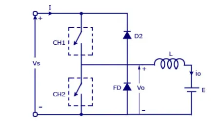
In this chopper, the average voltage will be always positive but the average load current will be positive or negative. The two switches CH1 and CH2 should not be turned ON simultaneously as the combined action may cause a short circuit in supply lines. For regenerative braking and motoring, this type of chopper configuration is used.
Develop a 2-quadrant chopper using Simulink:
The blocks used to develop this model are given below.
Pulse generator(I set amplitude=10, period time=0.1sec, pulse width=50)
DC voltage source(50V)
DC load voltage source(25V)
powergui
Series RLC branch(induction 1e-3)
MOSFET ( disable the show the measurement port and keep all value as it is)
Diode ( disable the show the measurement port and keep all value as it is)
logical operator(change to NOT)
scope(for result)
current measurement(for measurement )
voltage measurement( for measurement )
The circuit diagram for the 2 quadrant chopper is given below.
Now connect these blocks as shown below figure.
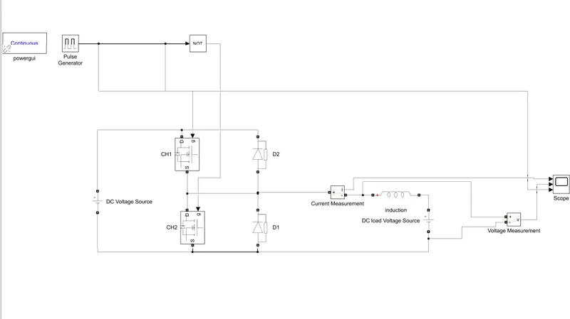
Here we use logical operator NOT because in this chopper we have 50 ON and 50 OFF in pulse width So when 50 ON is given to CH1 and 50 ON of NOT means 50 OFF will be given to CH2. Then 50 OFF is given to CH1 and 50 OFF of NOT means 50 ON is given to CH2. This is how the 2 quadrant chopper works.
We will always get positive output voltage as the D1 is present across the load. when the chopper CH1 is ON the current flows from the DC voltage source load. The inductor stores energy. When CH1 turns OFF the D1 means the freewheeling diode starts conducting and the output voltage will be equal to the source voltage. The direction of load current will be reversed.The load current will be flowing towards the source. The load current will be negative when CH2 is ON. The current completes its path through D2.
RESULT:
IN scope we see waveforms for current, voltage, and pulse generator.
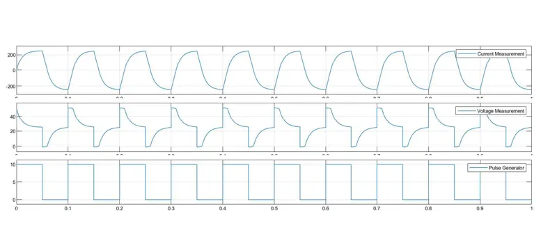
here I give stop time as 1 sec so we can see the waveform of current measurement it is increasing when CH1 is ON and voltage is decreasing 50V to 25V. Then The direction of load current will be reversed. The load current will be flowing towards the source. The load current will be negative when CH2 is ON. The current completes its path through D2.
3. Explain in a brief the operation of the BLDC motor.
ANS)
BLDC motor is a Brushless DC motor.
BLDC motors have many similarities to AC induction motors and brushed DC motors in terms of construction and working principles respectively. Like all other motors, BLDC motors also have a rotor and a stator.
Operation of the BLDC motor:
The underlying principles for the working of a BLDC motor are the same as for a brushed DC motor. In the case of a brushed DC motor, feedback is implemented using a mechanical commutator and brushes. With an in BLDC motor, it is achieved using multiple feedback sensors. The most commonly used sensors are hall sensors and optical encoders.
If the direction of the magnetic field is reversed, the voltage developed will reverse as well. For Hall-effect sensors used in BLDC motors, whenever rotor magnetic poles (N or S) pass near the hall sensor, they generate a HIGH or LOW-level signal, which can be used to determine the position of the shaft.
In a commutation system – one that is based on the position of the motor identified using feedback sensors – two of the three electrical windings are energized at a time as shown in figure 4.
In figure 4 (A), the GREEN winding labeled “001” is energized as the NORTH pole, and the BLUE winding labeled as “010” is energized as the SOUTH pole. Because of this excitation, the SOUTH pole of the rotor aligns with the GREEN winding and the NORTH pole aligns with the RED winding labeled “100”. In order to move the rotor, the “RED” and “BLUE” windings are energized in the direction shown in figure 4(B). This causes the RED winding to become the NORTH pole and the BLUE winding to become the SOUTH pole. This shifting of the magnetic field in the stator produces torque because of the development of repulsion (Red winding – NORTH-NORTH alignment) and attraction forces (BLUE winding – NORTH-SOUTH alignment), which moves the rotor in the clockwise direction.
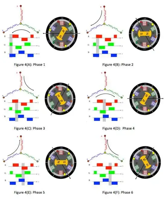
This torque is at its maximum when the rotor starts to move, but it reduces as the two fields align to each other. Thus, to preserve the torque or to build up the rotation, the magnetic field generated by the stator should keep switching. To catch up with the field generated by the stator, the rotor will keep rotating. Since the magnetic field of the stator and rotor both rotate at the same frequency, they come under the category of synchronous motor.
This switching of the stator to build up the rotation is known as commutation. For 3-phase windings, there are 6 steps in the commutation; i.e., 6 unique combinations in which motor windings will be energized.