Week-7 Challenge: DC Motor Control
SOLUTION 1.
BJT-H Bridge:-
The Bipolar Junction Transistor(BJT) when used for power switching applications, operates as an IGBT. When it is conducting (BJT operating in the saturated region), a forward voltage Vf is developed between collector and emitter(in the range of 1 V). Therefore the IGBT block can be used to model the BJT device.
The IGBT block does not simulate the gate current controlling the BJT or IGBT. The switch is controlled by a Simulink signal(1/0). The DC motor uses the pre-set model (5HP,24V 1750rpm). It simulates a fan type load(where load torque is proportional to the square of speed). The armatures mean the voltage can be varied from 0 to 240V when the duty cycle(specified in the pulse generator block) is varied from 0 to 100%.
The H-Bridge consists of four BJT/diode pairs(BJT simulated by IGBT models). Two transistors are switched simultaneously: Q1 & Q4 or Q2 & Q3. When Q1 and Q4 are fired, a +ve voltage is applied to the motor and diodes D2-D3 operate as free-wheeling diodes when Q1 &Q4 are switched off. When Q2 & Q3 are fired, a negative voltage is applied to the motor and diodes D1-D4 operate as free wheeling diodes when Q2 & Q3 are switched off.
CHOPPERS:-
A DC chopper is also known as a DC-DC converter. It is a static device that is used to obtain variable DC voltage from a constant DC voltage source. A DC-DC converter is an electronic circuit or electromechanical device that converts a source of direct current (DC) from one voltage level to another. It is a type of electric power converter. Power levels range from very low (small batteries) to very high (high voltage power transmission). Choppers are of two types:-
- Step down choppers
- Step up choppers
PROCESS:-
1)Explain and Run MATLAB demo 'Speed Control of a DC motor using BJT-H Bridge'.The armature current shoots up from the results are to be observed.
- open the MATLAB and in the help documentation type "Speed Control Of DC motor" using the BJT-H Bridge.
- Result tab opens, and then select the model and click open model.
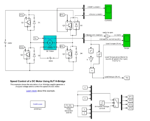
- The model is opened in a Simulink workspace.
- Run the model as it is and observe the graphs of the armature current.
- Now, at the bottom part of the model, there's a pulse generator block, click on it and run the model.
- Check the outputs. Follow the same for 75% and 50%, just to check if the armature voltage is decreased sharply after half of the simulation time.
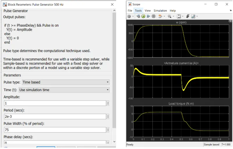
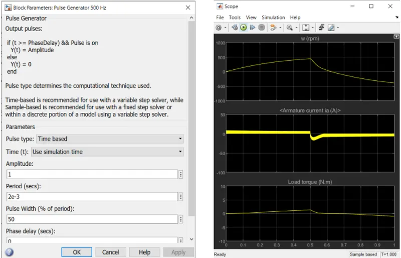
From the above graph as the pulse width decreases the steep value of armature current decreases.
SOLUTION 2.
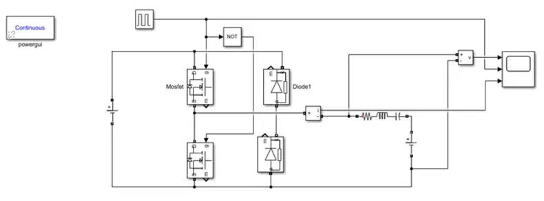
The Two-Quadrant Chopper DC Drive (DC6) block represents a two-quadrant DC-supplied chopper (or DC-DC PWM Converters) drive for DC motors. This Drive features Closed loop speed control with two Quadrant operations. The speed control loop outputs the reference armature current of the machine. Using a PI current controller, the chopper duty cycle corresponding to the commanded armature current is derived.
This duty cycle is then compared with a sawtooth carrier signal to obtain the required PWM signals for the chopper.
The main advantages of this drive, compared with other DC drives, are its implementation simplicity and that it can operate in two quadrants (forward motoring and reverse regeneration).
In addition, due to the use of high switching frequency DC-DC converters, a lower armature current ripple (compared with thyristor-based DC drives) is obtained. However, for all two-quadrant DC drives, reversible & regenerative operations (reverse motoring & Forward regeneration), which are required in the most DC drives, can't be obtained.
The Two-Quadrant chopper DC drive block uses these blocks from the electric Drives/Fundamental Drives blocks library:
- Speed Controller(DC)
- Regulation Switch
- Chopper
SOLUTION 3.
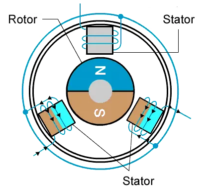
BRUSHLESS DC MOTOR (BLDC):-A brushless DC motor (known as BLDC) is a permanent magnet synchronous electric motor which is driven by direct current (DC) electricity and it accomplishes an electronically controlled commutation system (commutation is the process of producing rotational torque in the motor by changing phase currents through it at appropriate times) instead of a mechanically commutation system.
Unlike conventional brushed type DC motor, wherein the brushes make the mechanical contact with a commutator on the rotor so as to form an electric path between a DC electric source and rotor armature windings, BLDC motor employs electrical commutation with a permanent magnet rotor and a stator with a sequence of coils. In this motor, permanent magnet (or field poles) rotates and current-carrying conductors are fixed.
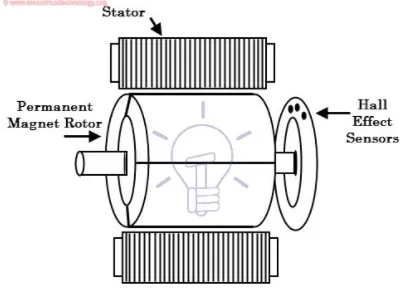
The armature coils are switched electronically by transistors at the correct rotor position in such a way that the armature field is in space quadrature with the rotor field poles. Hence the force acting on the rotor causes it to rotate. Hall sensors are most commonly used to sense the position of the rotor and are positioned around the stator. The rotor position feedback from the sensor helps to determine when to switch the armature current.
This electronic commutation arrangement eliminates the commutator arrangement and brushes in a DC motor and hence more reliable and less noisy operation is achieved. Due to the absence of brushes BLDC motors are capable to run at high speeds. The efficiency of BLDC motors is typically 85 to 90 percent.
Working Principle and Operation of BLDC Motor
BLDC motor works on the principle similar to that of a conventional DC motor, i.e., the Lorentz force law which states that whenever a current-carrying conductor is placed in a magnetic field it experiences a force. As a consequence of the reaction force, the magnet will experience an equal and opposite force. In the case BLDC motor, the current-carrying conductor is stationary while the permanent magnet moves.
When the stator coils are electrically switched by a supply source, it becomes an electromagnet and starts producing the uniform field in the air gap. Though the source of supply is DC, switching makes to generates an AC voltage waveform with a trapezoidal shape. Due to the force of interaction between the electromagnet stator and permanent magnet rotor, the rotor continues to rotate.
Here, one might get a question that how we know which stator coil should be energized and when to do. This is because; the motor's continuous rotation depends on the switching sequence around the coils. As discussed above that Hall sensors give shaft position feedback to the electronic controller unit.
Based on this signal from the sensor, the controller decides particular coils to energize. Hall-effect sensors generate Low and High-level signals whenever rotor poles pass near to it. These signals determine the position of the shaft.