Week -2
DETAILED REPORT ON SIMULINK MODEL OF DOORBELL USING SOLENOID BLOCK:-
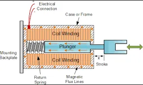
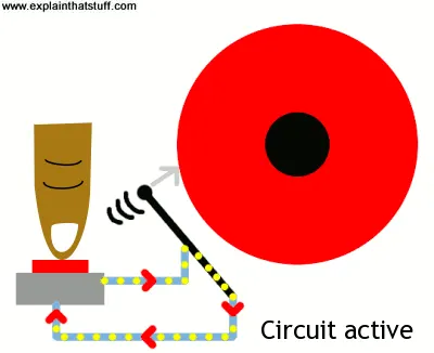
SOLENOID:- A solenoid is a device comprised of coil of wire(the housing) and a moveable Plunger(armature). When an Electric Current is introduced, a magnetic field forms around the coil which draws the plunger in. More simply,Solenoid Convert Electrical Energy into Mechanical work.
- The coil is made of many turns of tightly wound copper wire. When an electrical current flows through this wire, a strong magnetic field/flux is created.
- The housing, usually made of iron or steel, surrounds the coil concentrating the magnetic field generated by the coil.
- The plunger is attracted to the stop through the concentration of the magnetic field providing the mechanical force to do work.
SIMSCAPE & SIMULINK MODEL OF DOORBELL USING SOLENOID BLOCK:-
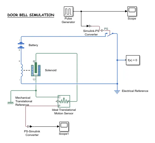
If you carefully observe the above Simulink Model, you will see there are two types of Circuits, which are highlighted by two Different colours:-
Green Colour----->Mechanical Circuit
Blue Colour ------>Electrical Circuit
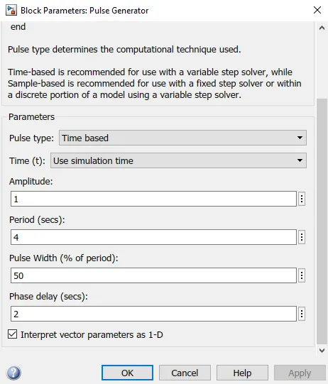
AS SITUATION GIVEN IN CHALLENGE THAT, SWITCH MUST BE CLOSED FOR 2SEC AND THEN RELEASED ,So for achieving that we have used a PULSE GENERATOR,and we will modify pulse width as such that pulse remain high for 2 sec.
NOW WE JUST GO THROUGH THE MAJOR SIMULINK AND SIMSCAPE BLOCKS THAT ARE USED IN SIMSCAPE AND SIMULINK MODEL:-
- SCOPE:-It will provide us graphical representation of outputs and inputs.
- PS-SIMULINK AND SIMULINK-PS CONVERTER:-Output and Input converter from physical system to simulink signals and vice-versa.
- PULSE GENERATOR:-This block generates pulses continuously, which we feed to a simple Electronic Switch as input, so that switch can become open for 2 sec and then closes for 2 sec.
- ELECTRICAL AND MECHANICAL REFERENCES:-We are using these References to Ground the Electrical and Mechanical Circuits.
- SOLENOID:-It is an Electromagnetic Device, that is used for converting the Electrical Energy to Mechanical work.
- BATTERY:- It is the main source of Excitation in the circuit, it is used for Energizing the circuit.
- SWITCH:-It is device which is used to energize and de-energize the circuit.
- IDEAL TRANSLATIONAL MOTION SENSOR:-This device is used for dectection of motion of Plunger of Solenoid.
- SOLVER CONFIGURATION:-It is a type of Block that act as a complete equation for where f(x)=0 where we find the value of x and Generate the output which represents the block diagram as an Equation.
GRAPHICAL REPRESENTATION OF OUTPUT OF PULSE GENERATOR:-
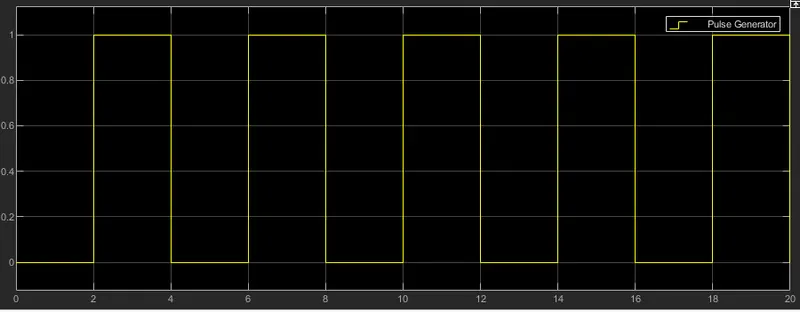
The above graph clearly showing that pulse generator is generating pulse for 50% of total time duration of a period ie 4sec, pulse is active for 2sec and remain passive for 2 sec. This pulse is then applied to input of switch so that switch can get energized.
GRAPHICAL REPRESENTATION OF TRANSLATIONAL MOTION OF PLUNGER OF SOLENOID:-
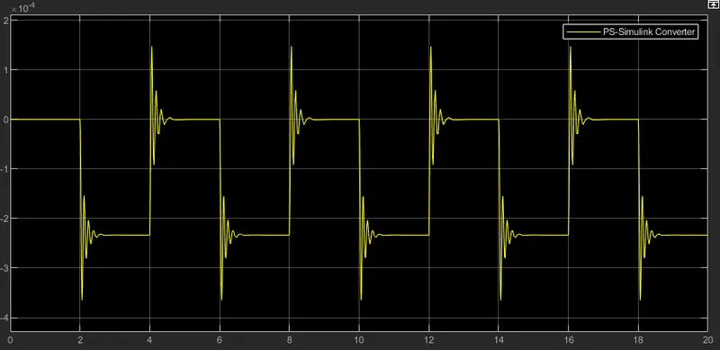
Above Graph clearly showing the fact that when the switch is closed then circuit gets energized and due to this ,plunger experiences strong electromagnetic force and start a translational motion.
You also observe that above graph is showing translational motion below the '0'-axis, ie negative direction of y-axis, But direction is not our concern, we are interested in translational motion of plunger in any direction.
Also notice that, we are receiving output only at those instances where the switch is closed OR when we are providing the input pulses only.
CONCLUSION:-
SO BY PERFORMING SIMSCAPE AND SIMULINK MODEL OF DOOR BELL WE EXACTLY KNOW HOW PRACTICAL DOOR BELL OPERATES. WE ALSO LEARNT ABOUT SOLENOID AND ITS WORKING PRICIPLE, WE ALSO VERIFY THIS MODEL GRAPHICALLY ALSO BY OBSERVING GRAPHS OF INPUT AND OUTPUT.
DETAILED REPORT ON WORKING OF THERMISTER TO SENSE THE TEMPERATURE OF A HEATER & TURN ON & OFF THE FAN AS PER GIVEN CONDITION:-
THERMISTOR:- A Thermistor was first discovered by Michael Faraday in 1833 on a silver sulfide which showed a behaviour of decrease in resistance when temperature increased.
Thermistor is a semiconductor device.
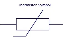
There are two types of Thermistors
NTC(Negative Temperature Co-efficient):-Resistance value decreases with increase in temperature. It is most widely used in industries like Temperature measurements,Temperature Control etc.
PTC(Positive Temperature Co-efficient):-Resistance Value increases with increase in Temperature.It is used in circuit Protection & current limiting resistors.
Thermistor have high sensitivity which can be upto 10% change per degree celsius. Thermistor physical response time is 0.5 to 5sec.
With an operating range from -50 Degree Celsius to -300 Degree Celsius and there are Devices with more Capacity.
NAME OF THERMISTOR GIVES YOU ENOUGH INFO:-
NTC------>Negative Temperature coefficient Resistor
10-------->Resistance value 10ohm
D-13----->Diameter of chip is 13.
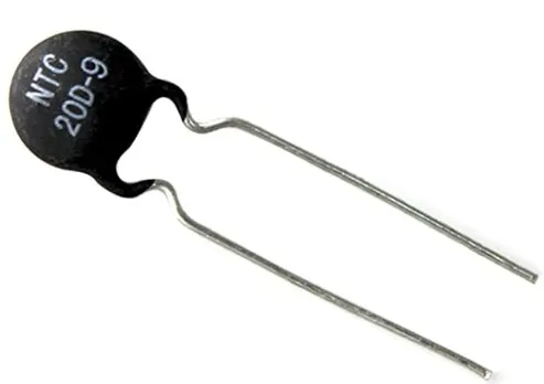
All manufacturers will represent their optimum condition for the Thermistor to maximum condition in their Datasheets.
TEMPERATURE SOURCE: 20 deg celsius from 0 to 10sec
:27 deg celsius from 10 to 30 sec
:23 deg celsius from 30 to 50 sec
Fan Conditions: ON if the temperature above 25 deg celsius, OFF otherwise.
LIST OUT ALL THE BLOCKS REQUIRED FOR THE PROBLEM:-
SIGNAL BUILDER:- To generate the signals according to the input condition given .
PS- SIMULINK CONVERTER:-Convert Simulink signals to the respective physical signals.
CONTROLLED TEMPERATURE SOURCE(CTS):- Provide a temperature physical output based on the condition given to port S.
THERMAL REFERENCE:-Thermal reference block provides the required initial conditions to the connected thermal block for the solver.
THERMISTOR:- Thermistor block which shows us the NTC thermistor relation between temperature & resistance.
BATTERY:-Battery is the storage device that provides the required voltage based on the parameter given. We can use DC voltage source blocks too.
RESISTOR:-Resistor which provides the opposing nature of current in a circuit.
VOLTAGE SENSOR:-This is used to measure the voltage or potential difference across any electrical component and it should connect in parallel only.
ELECRICAL REFERENCE:- These domain specific electrical reference blocks will provide the required initial Conditions to the connected thermal block for the solver.
SOLVER CONFIGURATION:-The solver configuration block specifies the solver parameters that your model needs before you can begin simulation & this is mandatory for all simscape designs.
PS-SIMULINK CONVERTER:- Converts physical signals to the respective simulink signal.
CONSTANT:-Provides a constant output value.
SWITCH:- This block has three input's namely port1, port2 & port3. Port 2 is the Control input, if the signal given to port 2 is satisfied with the condition & threshold of the switch block then it passes.Port 1 as output and if it is not satisfied then it will pass Port 3 as output.
SCOPE:- This is an output block that shows the signal with respective time in an x-axis.
SIMSCAPE AND SIMULATION MODEL OF THERMISTOR TO SENSE THE TEMPERATURE OF A HEATER & TURN ON (or) TURN OFF THE FAN AS PER THE BELOW CONDITIONS:-
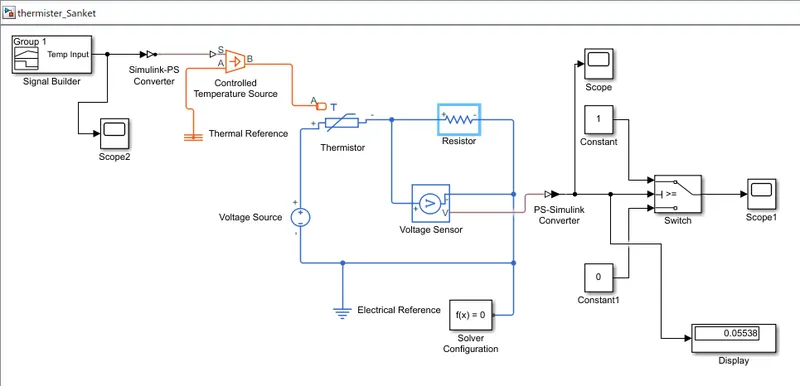
EXPLAINATION:-
- Above Model uses a Thermistor, to sense the Temperature of a heater .
- Here in this case, we have already defined the temperature of heater wrt time,
20 degree celsius----->0 to 10 sec
27 degree celsius----->10 to 30 sec
23 degree celsius----->30 to 50 sec
- And if Temperature exceeds 25 degree celsius then a signal must be given to some cooling arrangements so, that Fan can gets turn ON.
- For thermistor to sense the Temperature, we need to provide the signals to "CONTROLLED TEMPERATURE SOURCE".
- We use SIGNAL BUILDER BLOCK to create desired type of signal and feed this signal to "CONTROLLED TEMPERATURE SOURCE".Before feeding this signal to Controlled Temperature Source Block, we have to convert these signals into Physical value, so to do this we have to use a "SIMULINK-PS CONVERTER BLOCK."The output of CONTROLLED TEMPERATURE SOURCE is connected to THERMISTOR.
- We have provided a resistor in series with thermistor, and by using voltage sensor we measure the voltage drop accross this resistor. The value of this drop will act as threshold value for switch to operate on i.e is drop value is less that threshold value then switch gives ZERO indication & if drop value is greater than threshold value then switch gives UNITY indication.
- This 'ZERO'& 'UNITY ' indication will be used as "OFF"&"ON" switch for fan in cooling system.
GRAPHICAL REPRESENTATION OF INPUT PULSE :-
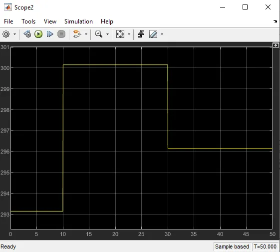
We know that 1 degree celsius=274 kelvin .
As by default Thermistor take value in Kelvin only so we need to convert all the temperature to kelvin scale.
GRAPHICAL REPRESENTATION OF VOLTAGE DROP ACROSS THE RESISTOR:-
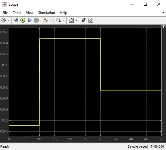
This is the Graphical Representation of VOLTAGE DROP across the RESISTOR connected in series across the THERMISTOR. This output is given to switch with threshold value will be 0.0645V. The switch will turn ON or OFF the fan according to the condition.
GRAPHICAL REPRESENTATION OF INPUT SIGNAL FOR COOLING SYSTEM FAN:-
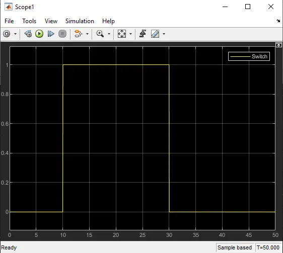
This output will be given to fan , here magnitude 1 indicates that fan will be in ON STATE and magnitude 0 indicates that fan will be in OFF state.
As in predefined situation, the fan will gets ON only when temperature exceeds 298 kelvin so , if you observe carefully between 10 sec to 30 sec the temperature is greater than 298 kelvin so during this duration fan gets ON otherwise it will remain in OFF state.
CONCLUSION:-
SO IN THIS CHALLENGE WE HAVE LEARN HOW TO BUILD THE SIMULATION & SIMSCAPE MODEL OF DOORBELL USING SOLENOID AND USING THERMISTOR SENSE THE TEMPERATURE OF A HEATER & TURN ON (OR) TURN OFF THE FAN AS PER GIVEN CONDITIONS.