Project
PROJECT AIM :- TO PREPARE A DETAILED TECHNICAL REPORT ON SIMULATION OF ALL TERRAIN VEHICLE(ATV) UNDER DIFFERENT RUNNING CONDITIONS AND EXPLAIN THE MODEL PROPERTIES WITH COMMENTS ON THE RESULTS.
ALL TERRAIN VEHICLE (ATV) :-
The term ATV stands for ALL TERRAIN VEHICLES. It is also known as a Quad or Quadricycle type vehicles.
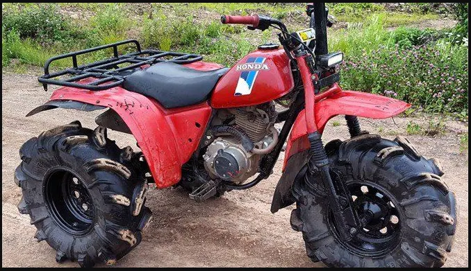
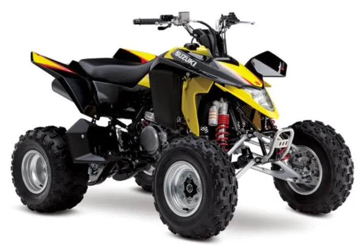
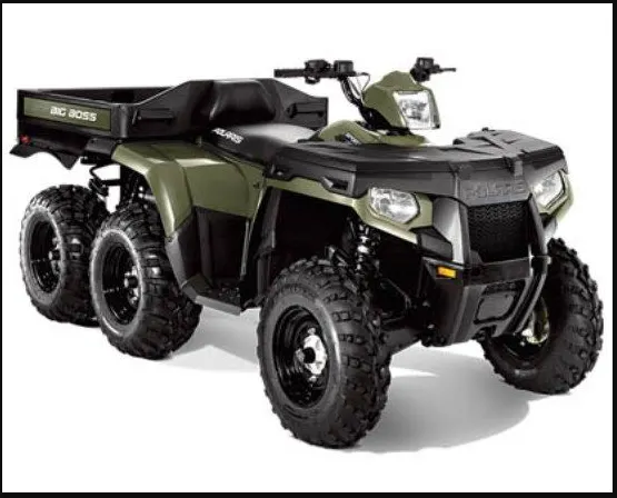
An All Terrain motor vehicles could have three, four or even six wheels.Unlike a motorcycle, generally the ATV's have more than two wheels.
This vehicle runs on low pressure tires. It has handle bars instead of wheel for controlling the steering.
As the name indicates, an ATV is designed to handle a broader variety of terrain than regular vehicles.In some countries it is street-legal motor vehicle & licensed for use on public roads. However it is not Street-Legal within some states, territories and provinces of some countries.
RIDING AN ATV :-
The riders ride an ALL TERRAIN VEHICLE by siting on it like a motorcycle. However you don't need much effort to balance it because extra wheels gives more stability at slower speed.
Most dirt bikes are considered the ATV's because they are designed for off road use only.Most ATV's come with three or four wheels.
However, some specialized applications requires six-wheel models. Engine sizes of ATV's ranges from as low as 49cc to 1000cc. However the size of engine depends on the application of ATV.
Generally the intended use of ALL TERRAIN VEHICLES is by a single operator only. However some manufacturers make ATV's for use by two. Of them, one is the operator & other is passenger.So manufacturers refers these ATV's as TENDEM ATV's. The rider or main operator must wear a helmet just like a motorcycle rider.
DEVELOPMENT :- The development of ATV started way back in the early 19th century.In 1893 Royal Enfield manufactured and sold the first powered quadricycle.The vehicle employed many bicycle component such as handle bars.
A group of students first designed a three wheeled ATV or Tri-Cartin as a collage project work. The tricart was a straddle ridden with a sit in rather than sit on type. Later many small manufacturers followed this trend and started making it.
Most earlier generation ATV's had large balloon tires instead of a mechanical suspension.However by the early 1980's manufacturers introduced ALL TERRAIN VEHICLES with better components like suspension, racks & lower profile tires.
In the late 1980's due to safety issues with three wheeled ATV's manufacturer upgraded them to four wheel models. Later manufacturers like POLARIS designed & developed the ATV's with six wheels for specialised operation such as military.
Modern ATV's employ advance features such as liquid-cooled engine & twin spark plugs. Some also offer Independent suspension,Automatic Transmission & a 4 wheel drive system etc. Manufacturers categorized modern ATV's in the following categories.
- Utility
- sport
- children's
- side-by-side or SxS
- 50cc gas
Honda, Suzuki,yamaha & kawasaki are some of the ATV manufactures in the world.
BAJA SAE :- BAJA SAE is college level Design Competition run by the society of automotive Engineers International(SAE International).
Teams of students from universities all over the world design and build small off road cars.The cars all have engines of same specifications.
The goal in BAJA SAE racing is to design, build and race off road vehicles that can withstand the harshest elements of rough terrain.The vehicles used BAJA SAE racing are often similar to DUNE BUGGIES. Before 2007, the events is named as "mini baja".
Each year as many as 141 BAJA cars are entered in the BAJA SAE events across the US & around the world.International Events are endorsed by SAE International and are held in Brazil,korea,south africa & mexico.
All cars must adhere to SAE International's rules and pass SAE's technical inspection & judging a car may not race untill all safety inspections are passed.
ORIGINS :-
The BAJA SAE Competition originated at the university of south carolina in 1976 under the supervision of Dr Harit Mehta.
OBJECTIVES :-
BAJA SAE is an intercollegiate engineering design competition for undergraduate & graduate Engineering students.
The object of the competition is to simulate real-world engineering design projects & their related challenges.Each team is competing to have its design accepted for manufacture by a fictitious firm.
The students must function as a team to design, build,test promote & compete a vehicles with-in the limits of the rules, also to generate financial support for their project and manage their Educational priorities.
Each team's goal is to design & build a prototype of a rugged, single seat, off-road recreational vehicles intended for sale to the non professional weekend off road enthusiast. The vehicle must be safe, easily Transported,easily Maintained & fun to drive. It should be able to negotiate rough terrain without damage.
STATIC EVENTS:-
The static events are usually held on the first two days of competition.Static Events consists of :- Technical Inspection, cost, design judging, and sales presentation.
DYNAMIC EVENTS:-
Dynamic events are usually held on he final two days of competition. The first dynamic day includes the following events:Acceleration, Hill Climb or Traction Event, Maneuverability, speciality Events(Rock crawl, mud bog & suspension).
MAJOR COMPONENTS USED IN THIS SIMULATION:-
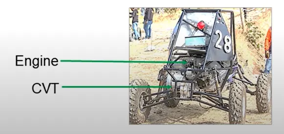
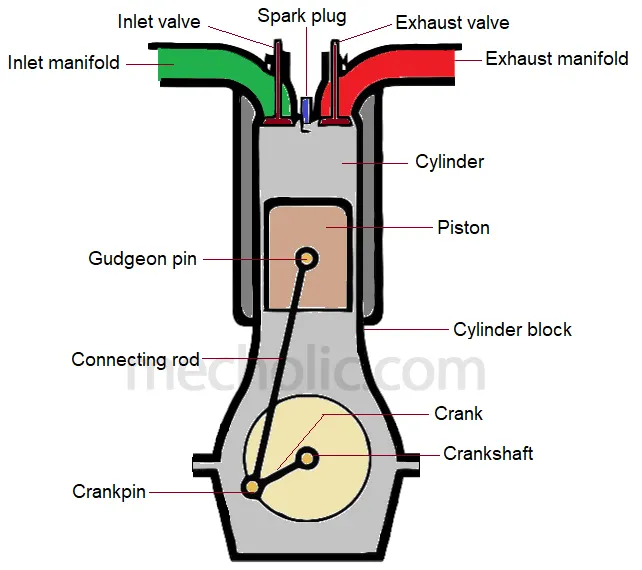
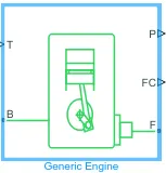
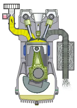
Generic Engine:-The Generic Engine block represents general IC engine. An internal combustion engine is an Engine in which ignition & combustion of fuel takes place inside the engine.It works on the principle that the charge is ignited inside a combustion chamber under very high pressure.
The engine is a mechanical component that converts one form of energy(Heat energy) into mechanical energy. These kinds of engines are popularly known as "Heat Engines". Basically, engines are of two types i.e:-
1.EC Engine
2.IC Engine
Both EC and IC are of two types i.e Reciprocating & Rotary Engines.
IC Engine acronym for an internal Combustion engine is the engine in which ignition and combustion of fuel takes place inside the engine.
SIMPLE GEAR:-
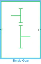
When there is only one gear on each shaft it is known as Simple gear train.The gears are represented by their pitch circles.When the distance between two shaft is small, the two gear 1 and 2 are made to mesh with each other to transmit motion from one shaft to the other.
CONTINUOUS VARIABLE TRANSMISSION:-
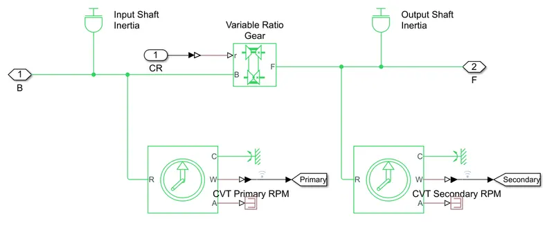
A CVT or Continuously variable transmission, seamlessly changes through an unending range of effective gear ratios while you drive, whereas other kinds of mechanical transmissions offer a fixed number of gear ratios & have hard shifts between each gears.
CVT transmission system are also known as single speed, shiftless and stepless transmissions.The shiftless nature of a CVT offers unparalleled flexibility that maintains constant angular velocity regardless of output speed.Additionally, a continuously variable transmission makes acceleration smooth and offers enhanced fuel economy.
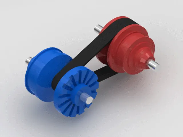
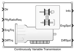
This system consists of cones at each pulley connected via chain belt .The cones can move to increase or decrease the belt diameter to change gear ratios, allow for quick shifting into the needed ratio for increased power, and boost fuel economy.
One pulley in the CVT is connected to the engine and the other directs power to the wheels. The width of these pulleys changes based on the needed power, as one gets larger the other gets smaller.This allows a CVT to deliver strong & seamless acceleration.
VEHICLE BODY:-
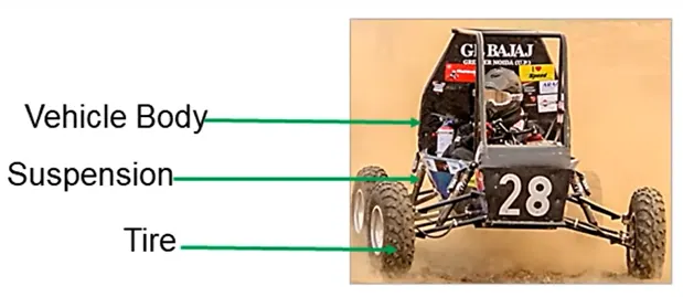
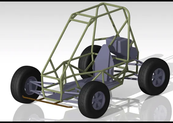
Vehicle Body means a body of vehicle meaning any device which was at one time capable of being drawn, propelled or driven by any kind of power and includes a recreational vehicle and a commercial vehicle.Vehicle body is the main supporting structure of a vehicle to which all other components are attached.
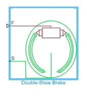
DOUBLE SHOE BRAKE:-
The Double Shoe brake block represents a frictional brake with two pivoted rigid shoes that press against a rotating drum to produce a braking action.
A positive actuating force causes the rigid shoes to press against the rotating drum.Viscous & contact Friction between the drum & the rigid shoe surfaces causes the rotating drum to decelerate.
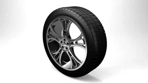
TIRE:-
A tire is a ring -shaped component that surrounds a wheel's Rim to transfer a vehicle's load from the axle through the wheel to the ground and to provide tractio n on the surface over which the wheel travels.
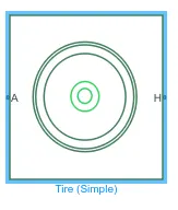
MAJOR BLOCKS INVOLVED IN THIS SIMULATION:-
SIGNAL BUILDER:-This allows you to create interchangeable groups of piecewise linear signal sources and use them in a model.
SIMULINK TO PS CONVERTER:-The PS-Simulink Converter block converts a physical signal into a Simulink output signal. Use this block to connect outputs of a Simscape physical network to Simulink scopes or other Simulink blocks.
SOLVER CONFIGURATION:-Each physical network represented by a connected Simscape block diagram requires solver settings information for simulation. The Solver configuration block specifies the solver parameters that your model needs before you can begin simulation.
MECHANICAL REFERENCE:-The Mechanical Rotational reference block represents a reference point, or frame,for all Mechanical rotational ports.The Mechanical Translational Reference block represents a reference point,or frame, for all mechanical translational ports.
GENERIC ENGINE:-The Generic Engine block represents a general internal combustion engine.It is used to run the engine with speed and torque values as input.
PS TO SIMULINK CONVERTER:-The PS-Simulink Converter block converts a physical signal into a Simulink output signal. Use this block to connect outputs of a Simscape physical network to Simulink scopes or other Simulink blocks.
SCOPE:-Scope blocks and Floating Scope blocks both display simulation results, but they differ in how you attach signals and save data. Simulation behavior for a Floating Scope and a Scope Viewer is identical, but you manage them differently in your model.
DISPLAY:-The Display block shows the value of the input data. You can specify the frequency of the display. For numeric input data, you can also specify the format of display.
INERTIA:-The physical force that keeps things where they are or keeps them moving in the direction they are travelling.
ROTATIONAL MOTION SENSOR:-The Rotary Motion Sensor lets you monitor angular motion precisely and easily. It is direction sensitive. You can use it to collect angular displacement, angular velocity, and angular acceleration data.
VARIABLE GEAR RATIO:- Variable Gear represents a gearbox that dynamically transfers motion and torque between the two connected driveshaft axes, the base and the follower.
PS TERMINATOR:-Use the PS Terminator block to cap physical signal output ports that do not connect to other blocks.However, you can use a PS Terminator block for clarity, to indicate that the signal was not inadvertently left unconnected.
DOUBLE SHOE BRAKE:-The Double-Shoe Brake block represents a frictional brake with two pivoted rigid shoes that press against a rotating drum to produce a braking action.
PS CONSTANT:-The PS Constant block generates a physical signal of a constant value. You specify the value and unit of the signal as the Constant parameter.
TIRE:-The Tire (Simple) block represents a simple, no-slip model of a tire that you parameterize by tire radius.You can optionally add inertia, stiffness, or damping. These dynamics require additional computation that tends to make models less suitable for real-time simulation.
ROTATIONAL FREE END:-The Rotational Free End block represents a mechanical rotational port that rotates freely, without torque.You can use this block to terminate mechanical rotational ports on other blocks that you want to leave unconnected.
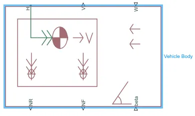
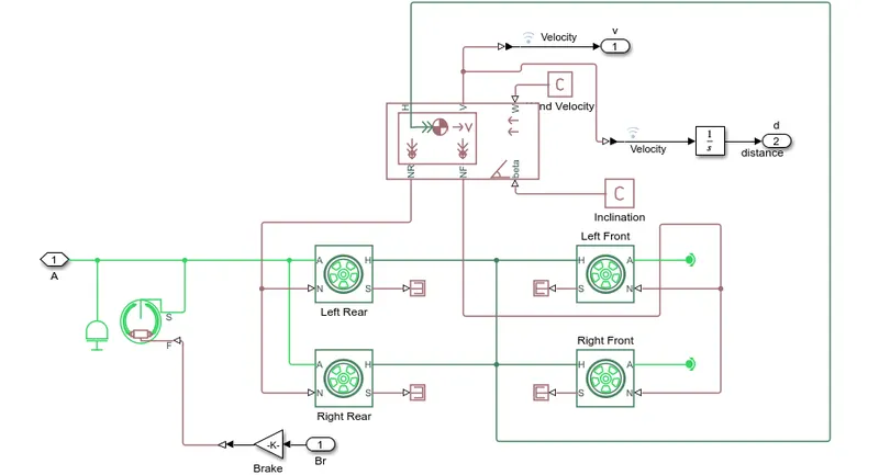
VEHICLE BODY:-The Vehicle Body block represents a two-axle vehicle body in longitudinal motion. The vehicle can have the same or a different number of wheels on each axle. For example, two wheels on the front axle and one wheel on the rear axle. The vehicle wheels are assumed identical in size.
CUSTOM MEASURE GAUGE:- To measure the Brake and Throttle input.
KNOB:-The Knob block tunes the value of the connected block parameter to during simulation. For example, you can connect the Knob block to a Gain block in your model and adjust its value during simulation. Use the Knob block with other Dashboard blocks to create an interactive dashboard to control your model.
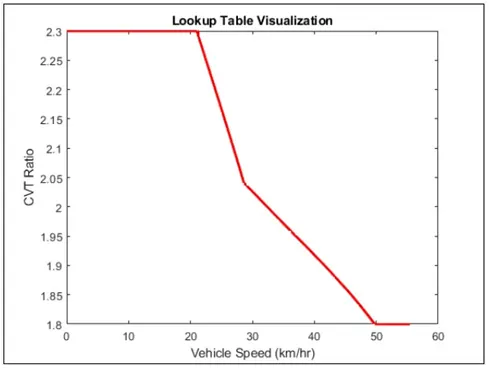
LOOKUP TABLE:-Use blocks from the Lookup Tables library to model nonlinearity. Lookup table blocks use arrays of data to map input values to output values, approximating mathematical functions.
SIMPLE GEAR:-The Simple Gear block represents a gearbox that constrains the connected driveline axes of the base gear and the follower gear to corotate with a fixed ratio that you specify. You choose whether the follower axis rotates in the same or opposite direction as the base axis.
STEP:-The Step block provides a step between two definable levels at a specified time.It is also used to increase or decrease an input value for a defined time interval.
TYPES OF MODELS:-
BAJA ATV without Dashboard
BAJA ATV with Dashboard
BAJA ATV model-Mapped Lookup Table with Dashboard.
BAJA ATV MODEL WITHOUT DASHBOARD
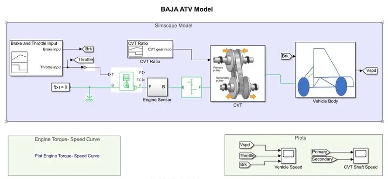
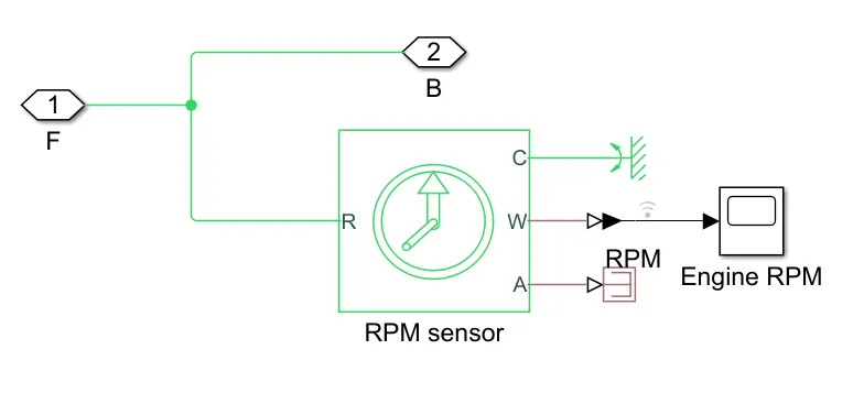
ENGINE SENSOR:-
This block measures the angular velocity or angle in a mechanical rotational network.The sensor is ideal since it does not account for inertia, friction,delays,energy consumption, and so on.
The physical signal ports W & A report the angular velocity and angular displacement, repectively of port R relative to port C.The measurement is positive when the motion at R is greater than the motion at C.
CONTINUOUS VARIABLE TRANSMISSION:-
VEHICLE BODY:-
SIMULATION PROCESS:-
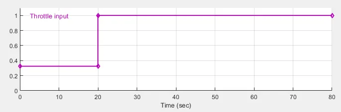
- The throttle signal is generated by signal builder block & inputted to generic Engine.
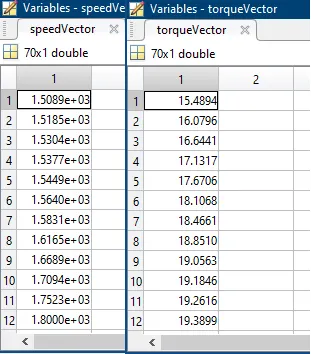
- The torque & speed vector are inputted from the MATLAB workspace.
- The engine will generate the output rpm which can be taken from the crankshaft output.This speed will be given to the Ideal Rotational Motion sensor to sense the output rpm.
- The same output speed will be given to a simple gear mechanism to reduce the speed where the gear ratio is '4'.
- Then the output speed from the gear reducer will be given to the Variable Ratio Transmission Block (CVT).
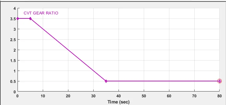
- The CVT ratio is provided to the Variable Ratio Transmission(CVT) block through signal Builder.
- The speed is Controlled by the variable CVT Ratios. and the controlled output speed is inputted to the vehicle axle.
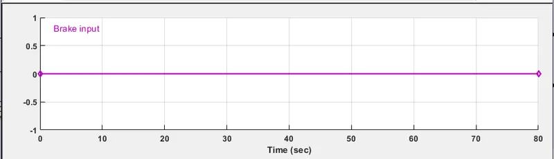
- The brake signal is generated by the signal builder and inputted to the vehicle body (Double shoe Brake) for applying the brake to axle.
OUTPUT:-
TORQUE-SPEED PLOT:-
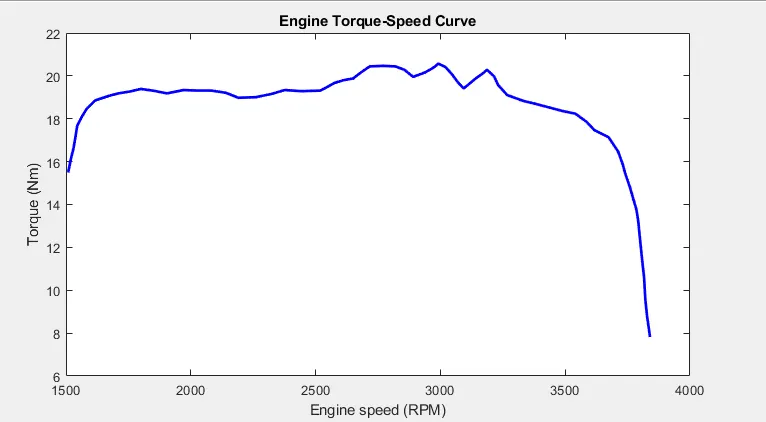
This graph is common for all the model's because it is a default input to the engine.
Inputs like Torque & Speed are generated From MATLAB workspace window and given to Generic Engine Block to generate the output RPM accordingly.
ENGINE SPEED PLOT:-
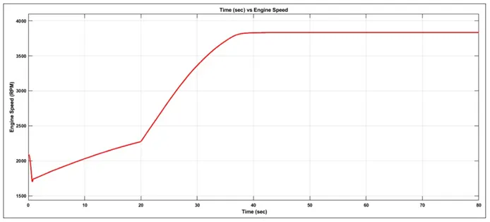
Engine RPM generated according to the throttle, speed & torque inputs.It is clearly showing that as the step increases in throttle at 20th second resulted in an increase in the Engine revolution.
ENGINE SPEED VS GEAR REDUCTION SPEED PLOT:-
Here we can see that Engine speed is reduced by the Gear Ratio '4' for verification we can calculate Max RPM
Maximum RPM (Before Reducing)=3833rpm
Gear Ratio=1:4
We know that
Driven = 3833/4 NOTE: [Driven=Secondary CVT Shaft]
Driven=95625 RPM [Driver=Primary CVT Shaft]
Thus, the reduced maximum rpm is 958.25 rpm which can be verified from the plot.
CVT SPEED REDUCTION PLOT:-
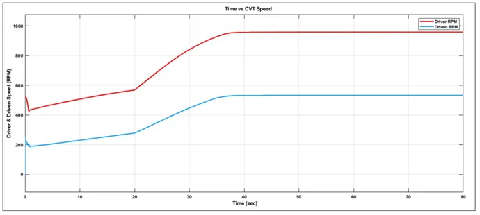
Reduced engine speed is controlled by various CVT ratios. For verification i had calculated the maximum RPM.
Max RPM(BEFORE REDUCING)=958.25rpm
CVT Ratio=1:1.8
We know that,
Driven=3833/4
Driven=95625 RPM
The reduced maximum rpm is 532.36 rpm which can be verified from the plot.
SPEED VS THROTTLE PLOT:-
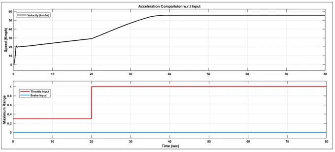
From carefully observing above graph we can conclude that brake is not applied during the driven cycle & the throttle is constant i.e 0.3 till 20 second and after 20 second throttle is increased from 0.3 to 1. and it remain constant for rest of the run.
With the increase in throttle value the vehicle speed also increases.
ACCELERATION PLOT:-
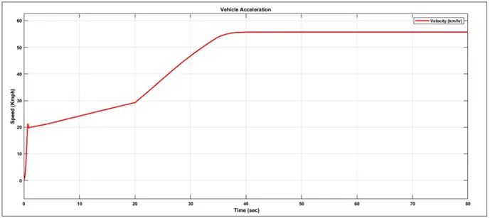
From the above plot, we can conclude that the vehicle is accelerated from 0-20kmph and then gradually increases till 30 kmph (approx) and it is accelerated to 55kmph and then it is constant throughout the cycle.
BAJA ATV MODEL WITH DASHBOARD
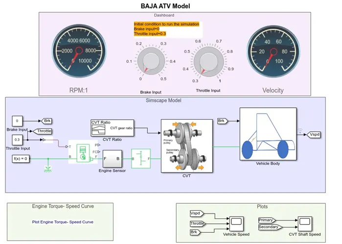
DASHBOARD:-
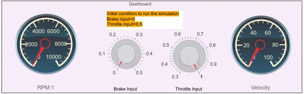
A dashboard is a visual display of all of your data... A dashboard usually sits on its own page and receives information from a linked database. In many cases it's configurable, allowing you the ability to choose which data you want to see and whether you want to include charts or graphs to visualize the numbers.
FLOW PROCESS:-
The model workforce process is as same as the process of BAJA ATV model without DASHBOARD. But the only difference is that Throttle & Brake inputs are controlled by the user & can be changed during simulation also by using knob.We are also replacing signal builder with two separate constant blocks for throttle and brake.
OUTPUT:-
ENGINE SPEED PLOT:-
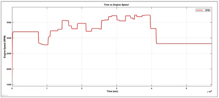
According to the inputs like throttle , break, torque & speed vectors the Engine speed is generated.As the runtime is not defined so the Throttle & break are controlled by the user.The step up is throttle and stepdown are break inputs.
ENGINE SPEED VS GEAR REDUCTION SPEED PLOT:-
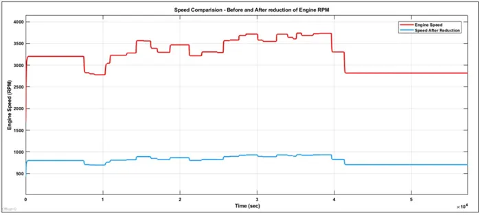
Here, we can see that the engine speed is reduced by the Gear Ratio '4'.For verification I calculated the Constant RPM (42000-50000 sec)
Maximum RPM (Before Reducing)=27593 rpm
Gear Ratio=1:4
We know that,
Driven=2759.3/4
Driven=689.825 RPM
The Reduced Constant RPM is 689.825 RPM which can be verified from the plot.
CVT SPEED REDUCTION PLOT:-
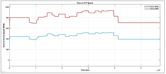
The Engine reduced speed is controlled by various CVT ratios. For verification i had calculated the constant RPM (42000-30000 sec)
Maximum RPM (BEFORE REDUCING)=689.825rpm
CVT Ratio=1:1.8
We know that DRIVEN =689.825/1.8 rpm
DRIVEN=383.23 rpm
The reduced maximum rpm is 383.23 rpm which can be verified from the plot.
SPEED VS THROTTLE PLOT:-
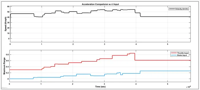
From the above graph we can observe that the vehicle is accelerating while throttle is applied (step up) and decelerated while Break is applied (Step Down).
ACCELERATION PLOT:-
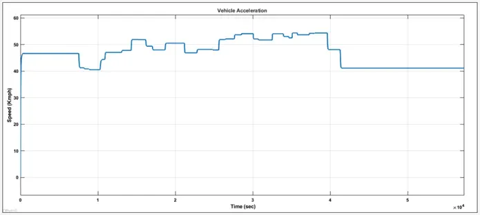
From the above graph we can infer that the vehicle is accelerated to 46 Kmph initially and then the state changes when the user controls the throttle and brake knobs. The step up is acceleration and step down are deceleration respectively. The linear one is the constant speed so no changes in throttle or braking.
BAJA ATV MODEL-MAPPED LOOKUP TABLE WITH DASHBOARD
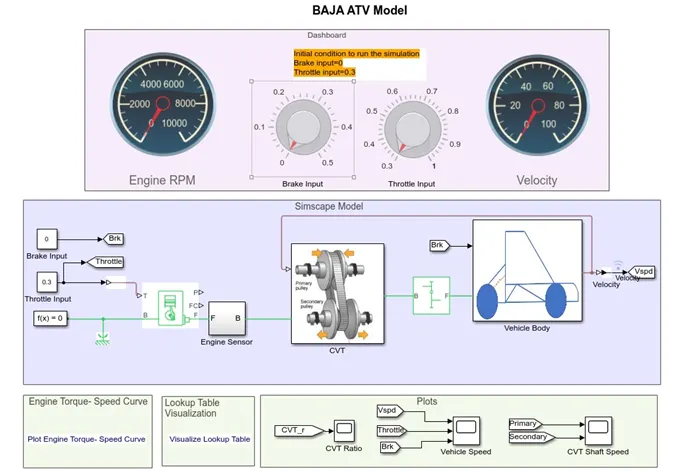
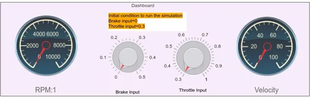
DASHBOARD DURING OFF CONDITION:-
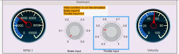
DASHBOARD DURING ON CONDITION:-
FLOW PROCESS:-
The work flow process is same as the process of BAJA ATV model with DASH BOARD. A small modification is here is the CVT Ratio and Vehicle Speed are Extracted using "To workspace" Block.
Instead of a "Signal Builder block" for CVT Ratio, the 2-D lookup Table is used. The interpolation & Extrapolation methods are set to linear.
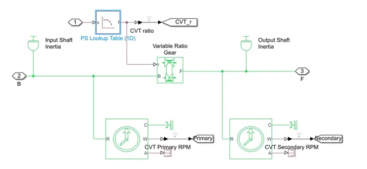
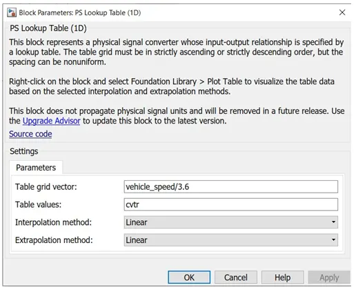
Right Click on the Lookup table block and choose foundation library option & then plot option to visualize the lookup table.
OUTPUT:-
ENGINE SPEED PLOT:-
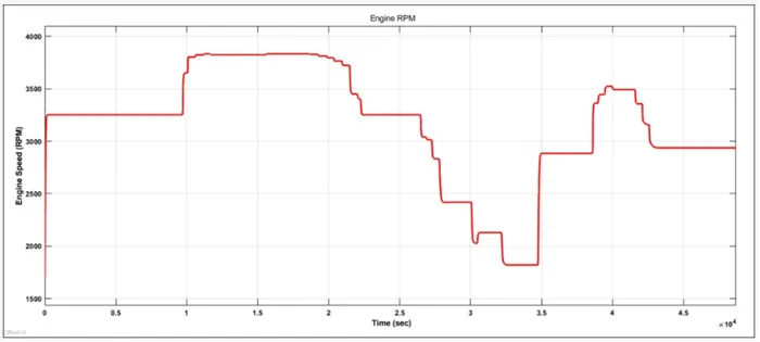
From the above graph we can infer that the vehicle was first running at minimum rpm of 3300rpm & then throttle is applied (step up), then braking (step down) then brake is released so that engine rpm is increased then braking is applied, then finally throttle and brake are put to constant of 2900 rpm.
CVT SPEED PLOT:-
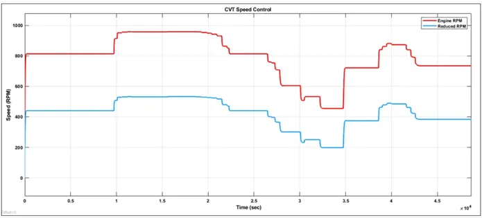
From the above graph, we can understand that the throttle is applied (step-up) and then kept constant, then braking is applied (step down) and finally brake is released so that the engine speed is increased with the increase in throttle input.
INPUT VS VEHICLE SPEED:-
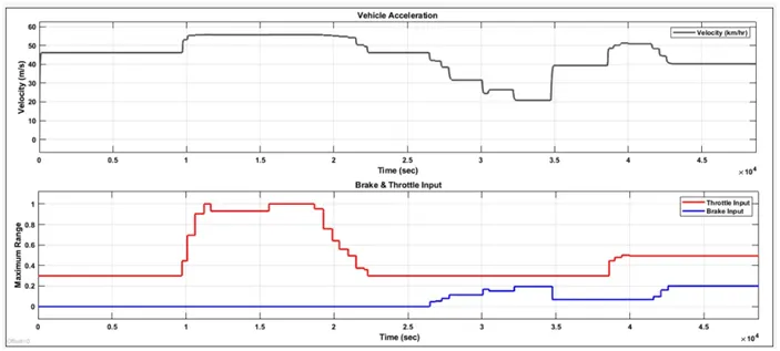
From carefully observing above plot we can infer that , when throttle is applied the vehicle speed increases & when Brake is applied , vehicle speed decreases simultaneously.
REFERENCES:-
- SIMULINK MODEL: BAJA ALL Terrain Vehicle (ATV) Model- File Exchange- MATLAB Central (mathworks.com)
- Modeling of a Continuously Variable Transmission (CVT) BAJA ALL Terrain Vehicle (ATV) video- MATLAB & Simulink (mathworks.com)
- Approximate one- dimensional function using specified lookup method- MATLAB- Mathworks India.
- IC engine with Throttle and rotational inertia & time lag- MATLAB Mathworks India.