Week-7 Challenge: DC Motor Control
Solution 1:- (A) The link of the model mentioned in the question is -"https://in.mathworks.com/help/physmod/sps/ug/speed-control-of-a-dc-motor-using-bjt-h-bridge.html".
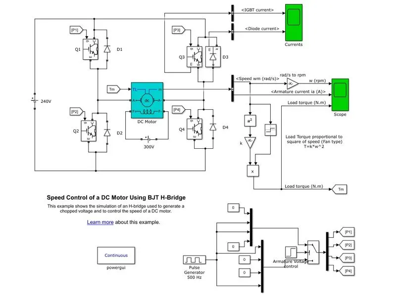
- The BJT (Bipolar Jucntion Transistor) when used for power switching applications, acts as an IGBT. When it is conducting (BJT operating in saturation region), a forward votage Vf is developed between collector and emitter (in the range of 1V).Therefore the IGBT block can be used to model the BJT device.
- The IGBT block does not simulate the gate current controlling the BJT or IGBT. The switch is controlled by Simulink signal (1/0).
- DC motor uses the preset model (5HP 240V 1750RPM). It simulates a fan type load (where load torque is proportional to square of speed). The armature mean voltage can be varied from 0 to 240V when the Duty Cycle (as specified in the Pulse generator) is varied from 0 to 100%.
- The H-bridge consists of 4 BJT /diode pairs(BJT simulated by IGBT). Two transistors are switched simultaneously:Q1 and Q4 or Q2 and Q3. When Q1 and Q4 are fired, a positive voltage is applied to the motor and diodes D2-D3 operate as free-wheeling diodes when Q1 and Q4 are switched off.
- When Q2 and Q3 are fired, a negative voltage is applied to the motor and diodes D1-D4 operate as free-wheeling diodes when Q2 and Q3 are switched off.
Simulation (Case 1):-
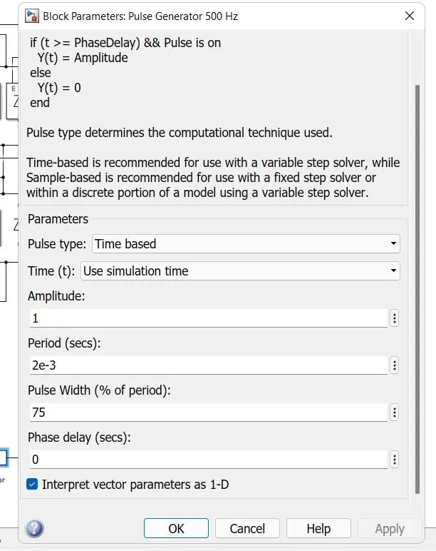
The motor starts in the positive direction with a Duty cycle of 75% (mean DC voltage of 180V) .At t=0.5sec, the armature voltage is suddenly reversed and the motor runs in the negative direction. The motor parameters in this case are as shown below:
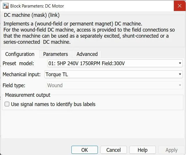
Solution 1:- (B) The following are the plots of the IGBT current and DIODE current:-
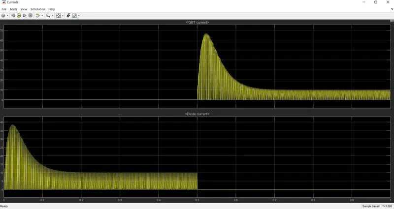
From the above plot, it can be seen that the IGBT current for Q3 suddenly shows an overshoot at t-0.5sec.This is due to sudden reversal of armature voltage. Also the diode current D3 is high at the starting (arounnd 38A) as the energy stored in the inductor (motor coil) is maximum at that time and decreases gradually.
The plots for the motor speed, armature current and load torque are shown below:-
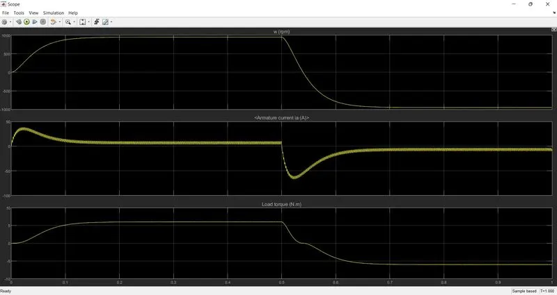
From the above plots the following conclusions can be made:-
- In the time period of (0,0.5sec), the motor speed is around 951rpm and it changes to around -951rpm when the armature voltage is reversed. This transition is not sudden due to the mechanical inertia of the rotor.
- During the transition, the armature current shows a negative peak of around 67A and also at the starting it is high to value of 38A. This overshoot in current is due to non-linearity of the magentic core as the motor speed and hence back EMF takes time to rise.
- It can also be concluded that the load Torque is similar in nature to the speed plot.
The high amount of currents obtained in the above plots can harm the motor windings and cause excessive heating which is undesirable. The same can be improved by doing the following alterations:-
Simulation (Case 2):- The shoot in armature current can be reduced by reducing the Pulse Width of the PULSE GENERATOR output. We change the Pulse generator width to 50%.
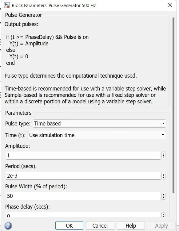
- The speed of motor can be regulated by using the above method known as PULSE WIDTH MODULATION.The inputs P1,P2,P3 and P4 are also changed according to the Drive Cycle.
The following are the simulation results after changing the Pulse Width:-
- IGBT CURRENT AND DIODE CURRENT
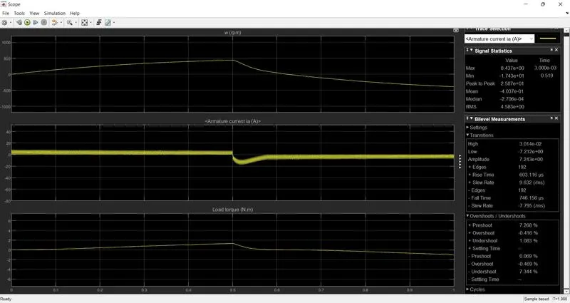
- MOTOR SPEED, ARMATURE CURRENT AND LOAD TORQUE
The following conclusions can be drawn from the above plots:-
- The negative peak of the armature current reduces to -17.4A from -67A as in the previous case with Duty Cycle of 75%
- In this observation starting currrent us generated as diode current for a time period of 0.5 sec, then IGBT current is acted while diode current is switched off.
- The graph shows the IGBT Q3 is switched off and Diode D3 is ON at the starting stage.
- Results show that voltage fluctuation is there in the starting point of Forward reverse state.
- A change is also held in speed and load Torque where a slightly less variation is observed as compared to 75% Duty cycle case .
- Time period of Forward and reverse action is maintained as in the previous duty cycle.
- In this observation, the shoot-up is reduced with the Undershoot of 7.344% as compared to 107% in the 75% Duty Cycle case.
Solution 1:- (C) "The Four-Quadrant Chopper DC Drive (DC7) block" :-
Four Quadrant operation of DC Motor:-
- The Four Quadrant operation of DC Motor means that motor V-I characteristics are obtained in all 4 quadrants. They are- Forward motoring, Forward braking, Reverse motoring, Reverse braking.
- A motor operates in two modes-Motoring and Braking, the Motor drive allows operation in both directions (forward and reverse) of rotation and of producing both motoring and regeneration is called as Four Quadrant Operation of DC Motor.
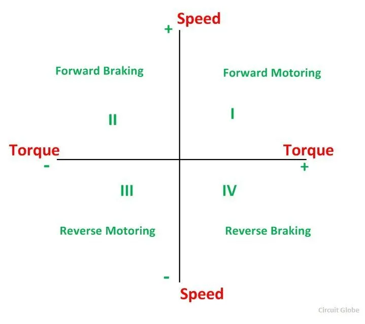
- QUADRANT 1:
- The power developed is positive and machine is working like a motor and supplying mechanical energy.
- The voltage and current are in the same direction.
- First Quadrant operation is known as Forward Motoring.
- QUADRANT 2:
- The second quadrant operation is known as braking.
- The direction of rotation is positive but the Torque us negative and thus the machine operates as a generator developing a negative Torque which opposes the motion.
- The Kinetic energy of the rotating parts is available as the electrical energy which may be supplied back to the mains.
- In dynamic braking the energy is dissipated in the resistance.
- The current direction is reversed keeping the voltage polarity the same.
- QUADRANT 3:
- The third quadrant operation is known as reverse motoring. The motor works in the reverse direction.
- Both the speed and Torque are negative while the power is positive.
- If the voltage polarity and the current is reversed simultaneously, the motor's operation will be in opposite direction. (but the power will be consumed by the load)
- QUADRANT 4:
- The fourth quadrant operation is known as reverse regenerative operation.
- If the voltage polarity is reversed maintaining the current direction same, the power is reversed and the operation is in 4th quadrant.
- In this operation the Torque is positive and the speed is negative. The motor operates in the reverse regenerative braking mode.
FOUR QUADRANT CHOPPER CIRCUIT DIAGRAM:-
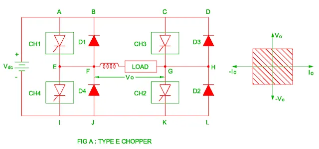
- The Type E chopper is a four quadrant chopper.
- It is a parallel combination of two type C choppers.
- The combination of chopper CH1, chopper CH2, diode D1 and diode D2 make the first type C chopper and the combination of chopper CH4, CH3, diode D4 and D3 make the other type C chopper.
WORKING/MODES OF CLASS E CHOPPER:-
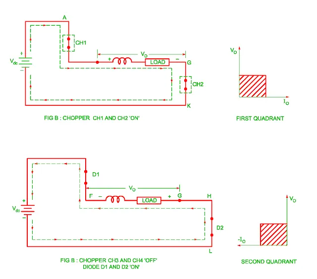
- When Switch CH1 and CH2 are turned ON at the same time, the inductor L will store its energy, both the voltage and current are positive and the chopper will work in the 1st Quadrant.
- When the Switch CH3 and CH4 are turned OFF at the same time, the inductor(polarity changes) dissipates its energy and diodes D1 & D2 conduct. The voltage is positive but the curent is negative making the operation in 2nd quadrant.
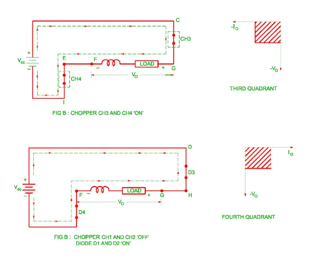
- When Switch CH3 & CH4 are turned ON at the same time, the inductor stores energy, both the voltage and current are negative and chopper operates in 3rd Quadrant.
- When Switch CH1 and CH2 are turned OFF at the same time, the inductor releases the stored energy and diodes D3 and D4 conduct. Here the output voltage is negative but the current is positive making the operation in 4th quadrant.
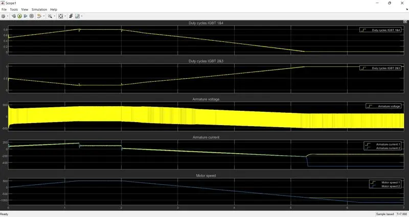
The Four-Quadrant Chopper DC Drive (DC7) block:-
Link:https://in.mathworks.com/help/physmod/sps/ug/dc7-four-quadrant-chopper-200-hp-dc-drive.html
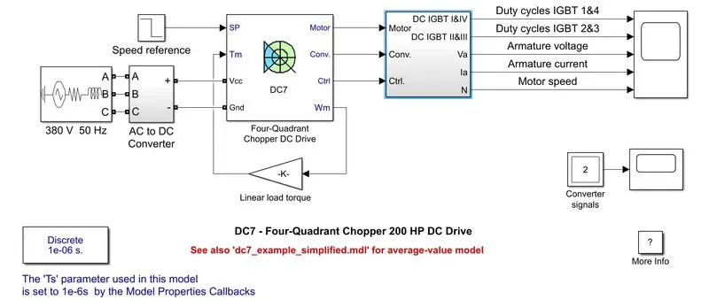
- The 200HP DC Motor is seperately excited with a constant 150 V DC field voltage source.
- The armature voltage is provided by an IGBT converter controlled by two PI regulators.
- The converter is fed by a 515V DC bus obtained on rectification of 380V, 50 Hz AC source.
- In order to limit the DC bus voltage during dynamic braking mode, a braking chopper has been added between the diode rectifier and the DC7 block.
- The first regulator is a speed regulator, followed by a current regulator. The speed regulator outputs the armature current reference (in p.u.) used by the current controller in order to obtain the electromagnetic torque needed to reach the desired speed.
- The speed reference change rate follows acceleration and deceleration ramps in order to avoid sudden reference changes that could cause armature over-current and destabilize the system.
- The current regulator controls the armature current by computing the appropriate duty ratios of the 5 kHz pulses of the four IGBT devices (Pulse Width Modulation).
- For proper system behaviour, the instantaneous pulse values of IGBT devices 1 and 4 are opposite to those of IGBT devices 2 and 3.
- This generates the average armature voltage needed to obtain the desired armature current. In order to limit the amplitude of the current oscillations, a smoothing inductance is placed in series with the armature circuit.
OUTPUT:-
COMPARISON OF DC CHOPPER DRIVE WITH H-BRIDGE:-
| BJT H-BRIDGE DRIVE | FOUR QUADRANT CHOPPER DRIVE |
| It is used for changing the direction of Motor(Forward or backward). | Here the Motor can be operated in 4modes (Forward and reverse motoring, forward and reverse braking). |
| Regenerative braking can not be obtained. | Regenerative braking can be achieved. |
| The source is of fixed DC supply. | The source is an AC supply which can be varied to rectified to varying DC supply. |
| The motor speed reference can not be fed. | The motor speed reference can be fed. |
| The armature current shoots up during the phase transition. | The armature current does not shoot up to the value of BJT H-bridge, but for low voltage the value is negigible. |
| Less control of the Vehicle. | Better control of the vehicle. |
| Signals are continous. | Signals are discrete. |
Solution 2:- THE SCHEMATIC OF 2 QUADRANT TYPE-C CHOPPER IS SHOWN BELOW:
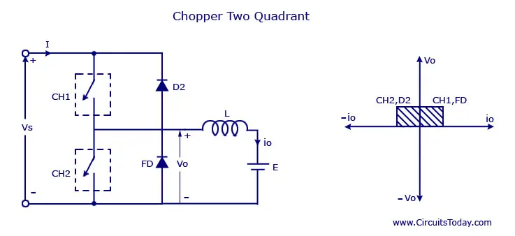
In this type of Chopper:-
- The average output voltage is always positive while the average output current may be positive or negative.
- The two switches CH1 and CH2 should not be turned on simultanously as it may cause short circuit.
- These are preferred for regenerative braking and motoring.
WORKING:-
- The FD present across the load always keeps the Vo positive.
- When CH1 is ON, current flows from source to load and the inductor stores te energy.
- When CH1 turned OFF, FD diode conducts and output voltage Vo=Vs.The direction of load current is reversed.
- When CH2 is ON, the load current will flow towards the source and Vo will still be positive.
- When CH2 is turned OFF, the load current flows through D2.
WAVEFORM:-
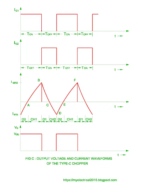
NOTE:- (D1 REPRESENTS FREEWHEELING DIODE FD)
SIMULINK MODEL:-
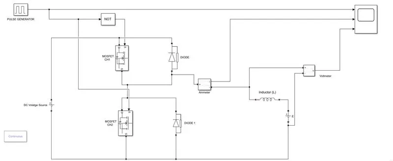
SIMULINK MODEL NAME: "TWO_QUADRANT_CHOPPER" (Attached below)
EXPLANATION OF MODEL CONSTRUCTION:-
- Arrange the above blocks as per the circuit diagram shown above.
- Double click on MOSFET and DIODE block to DISABLE uptick (show measurement port) and rotate the DIODE in upward direction as per the requirement.(Source should be facing downward direction for MOSFET for and upward for DIODE).
- Open the series RLC band block and change the branch type to L with default value 1mH.
- Open logical operator and select NOT in operations options. Connect its input to output of PULSE generator block. The reason for choosing NOT gate is to avoid the simultaneous operation of the two switches to avoid short circuit of supply.
- The voltage across the load is measured by connecting the input port 1 at starting of inductor and other at end of back EMF (E).
- The supply DC source is set to 24V and motor back EMF to 12V for analysis.
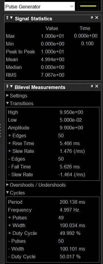
- Open the PULSE GENERATOR block and set the amplitude to 10, Duty Cycle to 50% and time period to 0.2sec.
- The simulation time is set to 10 sec.
OUTPUT RESULTS:-
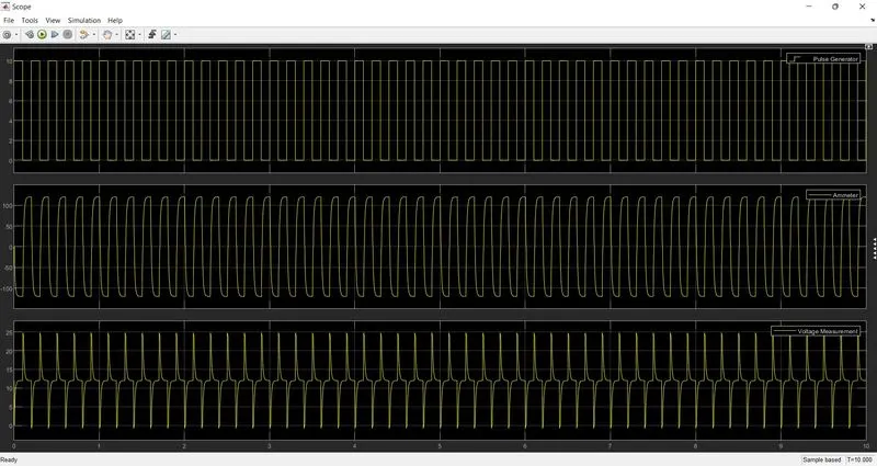
ZOOMED OUTPUT:-
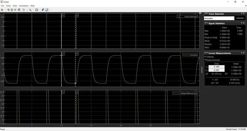
Current Measurement:-
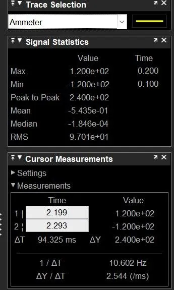
Voltage Measurement:-
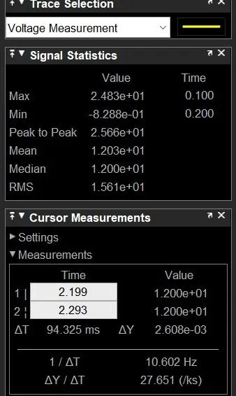
PULSE GENERATOR OUTPUT:-
CONCLUSIONS:-
- The width of the Gate pulses given to the switches is 100ms and the the period is 200ms.
- The output voltage across the load varies betweent the limits of 24.8A and -8.3A.
- The ouput current in the load varies between the range 120A to -120A.
- The chopper CH1 and DIODE1 conduct during the negative Pulse, while the chopper CH2 and DIODE2 conduct during the positive Pulse as per the connection.
- Whenever the current a steadt state value, the voltage waveform shows a peaky nature as is expected due to the inductive effect of the load inductance
Solution 3:- BRUSHLESS DC MOTOR (BLDC) :-
Introduction:- A brushless DC electric motor (BLDC motor or BL motor), also known as an electronically commutated motor (ECM or EC motor) or synchronous DC motor, is a synchronous motor using a direct current (DC) electric power supply. It uses an electronic closed loop controller to switch DC currents to the motor windings producing magnetic fields which effectively rotate in space and which the permanent magnet rotor follows. The controller adjusts the phase and amplitude of the DC current pulses to control the speed and torque of the motor. This control system is an alternative to the mechanical commutator (brushes) used in many conventional electric motors.
The construction of a brushless motor system is typically similar to a permanent magnet synchronous motor (PMSM), but can also be a switched reluctance motor, or an induction (aynchronous motor). They may also use neodymium magnets and be outrunners (the stator is surrounded by the rotor), inrunners (the rotor is surrounded by the stator), or axiall (the rotor and stator are flat and parallel).
The advantages of a brushless motor over brushed motors are high power-to-weight ratio, high speed, nearly instantaneous control of speed (rpm) and torque, high efficiency, and low maintenance. Brushless motors find applications in such places as computer peripherals (disk drives, printers), hand-held power tools, and vehicles ranging from model aircraft to automobiles. In modern washing machines, brushless DC motors have allowed replacement of rubber belts and gearboxes by a direct-drive design.
Construction Of a BLDC Motor:-
- BLDC motors can be constructed in different physical configurations. Depending on the stator windings, these can be configured as single-phase, two-phase, or three-phase motors. However, three-phase BLDC motors with permanent magnet rotor are most commonly used.
- The construction of this motor has many similarities of three phase induction motor as well as conventional DC motor. This motor has stator and rotor parts as like all other motors.
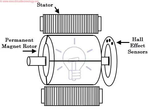
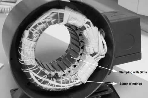
- Stator of a BLDC motor made up of stacked steel laminations to carry the windings. These windings are placed in slots which are axially cut along the inner periphery of the stator. These windings can be arranged in either star or delta. However, most BLDC motors have three phase star connected stator.
- Each winding is constructed with numerous interconnected coils, where one or more coils are placed in each slot. In order to form an even number of poles, each of these windings is distributed over the stator periphery.
Rotor:-
- BLDC motor incorporates a permanent magnet in the rotor. The number of poles in the rotor can vary from 2 to 8 pole pairs with alternate south and north poles depending on the application requirement. In order to achieve maximum torque in the motor, the flux density of the material should be high. A proper magnetic material for the rotor is needed to produce required magnetic field density.
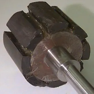
- Ferrite magnets are inexpensive, however they have a low flux density for a given volume. Rare earth alloy magnets are commonly used for new designs. Some of these alloys are Samarium Cobalt (SmCo), Neodymium (Nd), and Ferrite and Boron (NdFeB). The rotor can be constructed with different core configurations such as the circular core with permanent magnet on the periphery, circular core with rectangular magnets, etc.
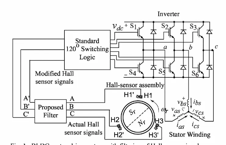
Hall Sensor Sequence Calibration of BLDC Motor
A Hall effect sensor varies its output voltage based on the strength of the applied magnetic field. According to the standard configuration, a brushless DC (BLDC) consists of three Hall sensors located electrically 120 degrees apart. A BLDC motor with the standard Hall placement (where the sensors are placed electrically 120 degrees apart) can provide six valid combinations of binary states: for example, 001,010,011,100,101, and 110. The sensor provides the angular position of the rotor in degrees in the multiples of 60, which the controller uses to determine the 60-degree sector where the rotor is present.
The target model runs the motor at a low speed (10 RPM) in open loop and performs V/f control on the motor. At this speed, the d-axis of the rotor closely aligns with the rotating magnetic field of the stator.
When the rotor reaches the open-loop position zero, it aligns with the phase a-axis of the stator. At this position (corresponding to a Hall state), the six-step commutation algorithm energizes the next two phases of the stator winding, so that the rotor always maintains a torque angle (angle between rotor d-axis and stator magnetic field) of 90 degrees with a deviation of 30 degrees.
The Hall sequence calibration algorithm drives the motor over a full mechanical revolution and computes the Hall sensor sequence with respect to position zero of the rotor in open-loop control.
Working Principle and Operation of BLDC Motor:-
- BLDC motor works on the principle similar to that of a conventional DC motor, i.e., the Lorentz force law which states that whenever a current carrying conductor placed in a magnetic field it experiences a force. As a consequence of reaction force, the magnet will experience an equal and opposite force. In case BLDC motor, the current carrying conductor is stationary while the permanent magnet moves.
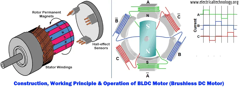
- When the stator coils are electrically switched by a supply source, it becomes electromagnet and starts producing the uniform field in the air gap. Though the source of supply is DC, switching makes to generate an AC voltage waveform with trapezoidal shape. Due to the force of interaction between electromagnet stator and permanent magnet rotor, the rotor continues to rotate.
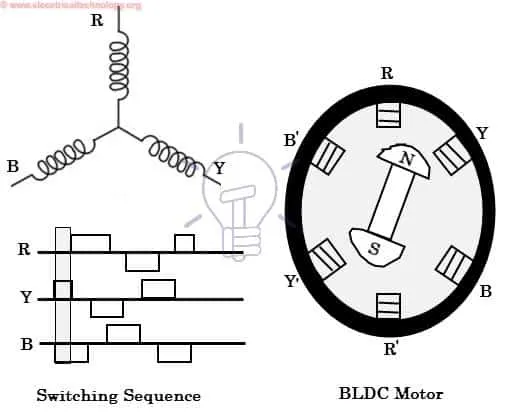
- Consider the figure below in which motor stator is excited based on different switching states. With the switching of windings as High and Low signals, corresponding winding energized as North and South poles. The permanent magnet rotor with North and South poles align with stator poles causing motor to rotate.
- Observe that motor produces torque because of the development of attraction forces (when North-South or South-North alignment) and repulsion forces (when North-North or South-South alignment). By this way motor moves in a clockwise direction.
Brushless DC Motor Drive:-
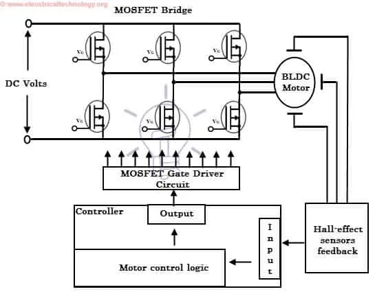
- As described above that the electronic controller circuit energizes appropriate motor winding by turning transistor or other solid state switches to rotate the motor continuously. The figure below shows the simple BLDC motor drive circuit which consists of MOSFET bridge (also called as inverter bridge), electronic controller, hall effect sensor and BLDC motor.
- Here, Hall-effect sensors are used for position and speed feedback. The electronic controller can be a microcontroller unit or microprocessor or DSP processor or FPGA unit or any other controller. This controller receives these signals, processes them and sends the control signals to the MOSFET driver circuit.
Advantages of BLDC Motor:-
- It has no mechanical commutator and associated problems
- High efficiency due to the use of permanent magnet rotor
- High speed of operation even in loaded and unloaded conditions due to the absence of brushes that limits the speed
- Smaller motor geometry and lighter in weight than both brushed type DC and induction AC motors
- Long life as no inspection and maintenance is required for commutator system
- Higher dynamic response due to low inertia and carrying windings in the stator
- Less electromagnetic interference
- Quite operation (or low noise) due to absence of brushes.
Disadvantages of Brushless Motor:-
- These motors are costly
- Electronic controller required control this motor is expensive
- Not much availability of many integrated electronic control solutions, especially for tiny BLDC motors
- Requires complex drive circuitry
- Need of additional sensors.
Applications of Brushless DC Motors (BLDC):-
Brushless DC Motors (BLDC) are used for a wide variety of application requirements such as varying loads, constant loads and positioning applications in the fields of industrial control, automotive, aviation, automation systems, health care equipments, etc. Some specific applications of BLDC motors are
- Computer hard drives and DVD/CD players
- Electric vehicles, hybrid vehicles, and electric bicycles
- Industrial robots, CNC machine tools, and simple belt driven systems
- Washing machines, compressors and dryers
- Fans, pumps and blowers