Week-7 Challenge: DC Motor Control
-
Aim:
1.A. explain a MATLAB demo model named ‘speed control of a DC motor using BJT H-bridge’
- comment on the armature current shoot-up from the scope results
- refer to the help section of ‘The Four-quadrant chopper DC drive block’. compare it with the H-bridge
- Develop a 2-quadrant chopper using Simulink & explain the working of the same with the relevant result.
- Explain in brief about operation of BLDC motor.
H-bridge circuit
first of all, let as understand the basic concepts of speed control using H bridge configuration. An H- bridge is a simple circuit that lets us to control a DC motor to go backward or forward.in general an H-bridge is a rather simple circuit, containing four switching element , with the load at the centre in an H-like configuration.
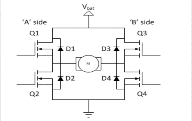
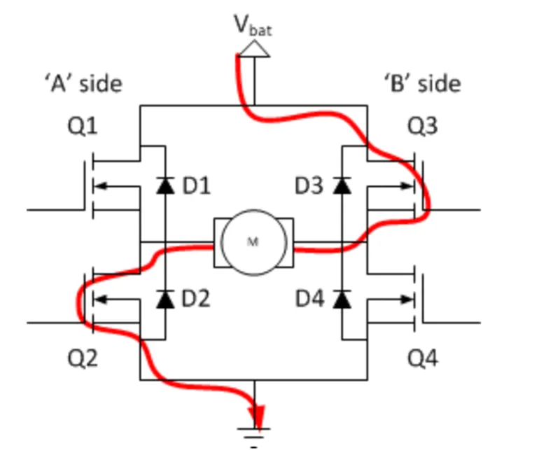
Q1 and Q2 are turned ON, the left of the lead of the motor will be connected to the power supply and right lead connected to gnd. Current starts flowing through the motor which energize the motor in forward direction.
If Q2 and Q3 are turned ON ,the revers will be happen the motor gets energized in the backwards.
Simulink model
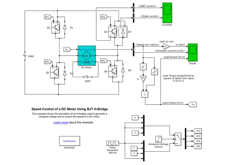
- The dc motor used is model present model (5HP 240V 1750rpm)
- The H-bridge consists of four BJT/Diode pairs. two transistor pairs are switched simultaneously. Such as Q1 - Q4 and Q2-Q3. when Q1 -Q4 is ON and Q2-Q3 is OFF the motor run in forward direction. Similarly Q2-Q3 is ON and Q1 - Q4 OFF the motor run in reverse direction
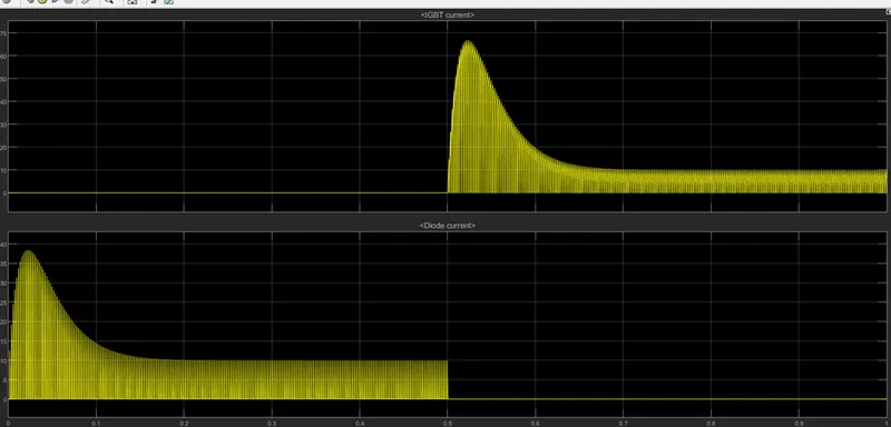
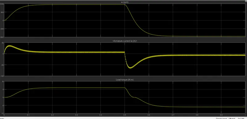
- The motor starts in the positive direction with duty cycle 75%.at 0.5sec the armature voltage is suddenly reversed and the motor runs in the negative direction.
1B)
From the armature current graph we can see that, at starting there is sudden spike increases in current at 0 sec also and at 0.5 sec also means at transition from positive to negative direction of rotation we observe a high surge in current, this is due to the transient switching occurring in the circuit.
In the above result the duty cycle selected as 75%.
Therefore, when the pulse width decreases the voltage applied across the DC motor decreases and the armature current finally decreases.
1c)
The four-quadrant chopper DC driver block represents a four-quadrant, DC-supplied chopper driver for DC motors.
The four-quadrant chopper dc driver block uses these blocks from the electric drivers /fundamental drive blocks library.
- Speed control
- Regulation switch
- Current control
- Chopper
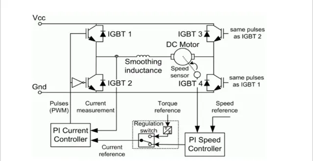
The above fig shows the schematic of the 4quadrant chopper DC driver
|
h-bridge |
4 quadrant chopper dc driver |
|
Only two quadrants of operation are possible They are forward and revers motoring |
it can operate in all four quadrants. they are forward, reverse regeneration, reverse motoring and forward generation |
|
higher armature current ripple |
Lower armature current ripple |
|
Less complex |
More complex |
|
Simulation is continuous and simulation time is more |
Simulation is discrete and simulation time is less |
|
Widely used in robotics |
Widely used in automobile |
Q2) type C chopper or two quadrant class A chopper
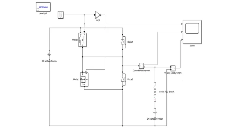
We know that class A and class B chopper operates in first and second quadrant respectively. Therefore, if we connect both these types of chopper in parallel then it is possible to have chopper operation in first as well as second quadrant.
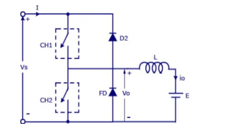
When chopper CH1 is switched ON source Vs get connected to the load and hence load voltage is equal to source voltage. The direction of load current is from source to load.
When CH1 is switched OFF the free-wheeling diode FD comes into the circuit as gets forward biased and. however the output voltage becomes zero.
When chopper CH2 is switched ON load DC source E drive current through CH2 and load. The direction of this current i0 will be opposite to that shown in circuit diagram hence is assumed negative. The output voltage is zero during this time.
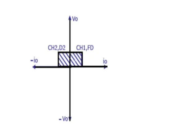
Caution: chopper CH1 and CH2 should not be ON simultaneously as this would lead to direct short circuit on the supply lines.
Application: class-C choppers are used for motor and regenerative breaking of DC motors.
The corresponding simulink model is shown below by using pulse generator alongwith NOT gate to pravent misfiring of the MOSFET.
link:https://drive.google.com/file/d/1xzLbCq9sSl-Tw_ue-4FiLYgGueDNbU4n/view?usp=sharing
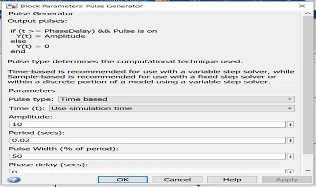
Pulse generator is used for switch ON and OFF the chopper circuit contoll input to the switch
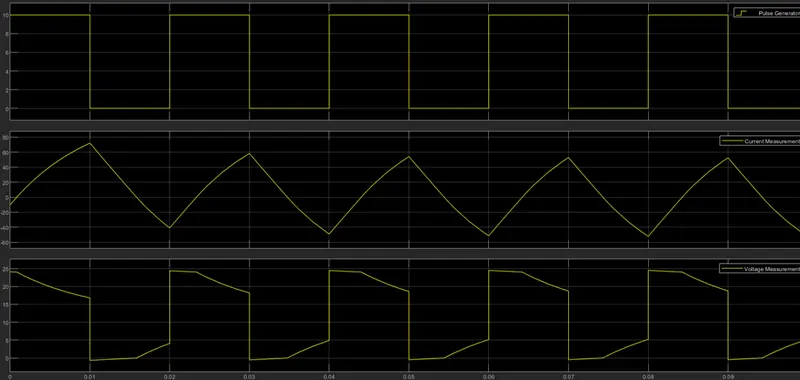
Hence seer the above output clearly the voltage is always positive but the current becomes both positive and negative. Hence type C chopper is simulated.
Q3)
BLDC MOTOR
Brushless dc motor also known as electrically commutated motors. the rotor is the sole bearer of the magnet and it does not require any power, no connection, no commutator, no brushes. this motor employs electrical communication with permanent rotor and a stator with a sequence of coil. In this motor permanent magnet rotates and current carrying conductors are fixed.
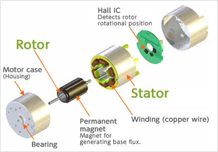
Brushless motor does not have any current carrying commutator. the field inside a brushless motor is switched through an amplifier which is triggered by the communication device like an optional encoder.
BLDC motor can be constructed in different physical configuration. Depending on the stator winding, two-phase, three-phase motors.
Working Of BlDC Motor
The underlying principle for the working of a BLDC motor are the same as for a brushed DC motor. the Lorentz force law which states that whenever a current carring conductor placed in a magnetic field it experiences a force. As a consequence of reaction force the magnet will experience an equal and opposite force. In BLDC motor the current carrying conductor is stationary and the permanent magnet is moving.
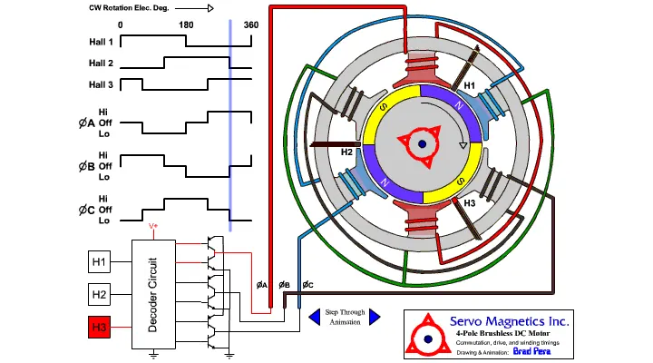
When the stator coil get a supply from source it becomes electromagnet and starts producing the uniform field in the air gap. Though the source of supply is DC switching makes to generate an AC voltage waveform with trapezoidal shape. Due to the force of interaction between electromagnet stator and permanent magnet rotor that continues to rotate.
With the switching of winding as high and low signals, corresponding winding energized as north and south poles align with stator poles which causes the motor to rotate.