Week-7 Challenge: DC Motor Control
.MODULE 1#
A. Explain a MATLAB demo model named ‘Speed control of a DC motor using BJT H-bridge’.
B. Comment on the armature current shoot-up from the scope results.
C. Refer to the help section of ‘The Four-Quadrant Chopper DC Drive (DC7) block’. Compare it with the H-bridge model.
Explain a MATLAB demo model named ‘Speed control of a DC motor using BJT H-bridge.
H-BRIDGE:
H-Bridge is a simple electronic circuit which enables us to apply voltage to load in either direction. It is commonly used in robotics application to control DC Motors. By using H Bridge we can run DC Motor in clockwise or anticlockwise directions. This circuit is also used to produce alternating waveforms in inverters.
BASIC H-BRIDGE CIRCUIT:
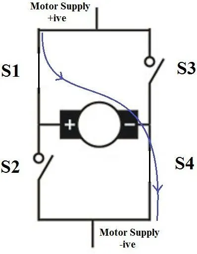
When switches S1 and S4 are switched on, motor runs in clockwise direction.
When S2 and S3 are switched on, motor runs in anticlockwise direction.
In actual practice these switches are replaced by transistors. Nowadays H Bridge ICs such as L293D and L293 are available.
below are the snap of basic h bridge ckt
t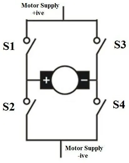
from above figure
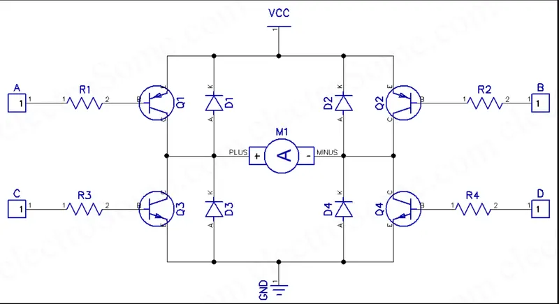
In this circuit all transistors are wired as switches. An NPN transistor (Q3 and Q4) will be ON when we give high voltage to it and a PNP transistor (Q1 and Q2) will be ON when we give LOW voltage to it. So when (A = LOW, C = LOW, B= HIGH, D = HIGH), transistors Q1 & Q4 will be ON and Q2 & Q3 will be OFF, so the motor rotates in clockwise direction. Similarly when (A = HIGH, C = HIGH ,B = LOW, , D = LOW), transistors Q2 & Q3 will be ON and transistor Q1 & Q4 will be OFF, thus the motor rotates in anticlockwise direction. 1N4148 (D1 ~ D4) is used as freewheeling diode as it is a fast switching diode. It avoids problems due to negative voltage produced by the back emf the dc motor. Resistors R1 – R4 are used to limit the input current of transistors and are designed in such a way that transistor will work as a switch. Transistor should be chosen according to the current requirements of the DC Moto.
WHY is a flyback diode necessary?
To protect the switch from being damaged due voltage spikes or inductive Flyback, a Flyback Diode or a Freewheeling Diode is used. The basic idea behind the use of a Flyback Diode is to provide an alternative path for the inductor for its current to flow.
SPEED CONTROL OF DC MOTOR USING BJT:
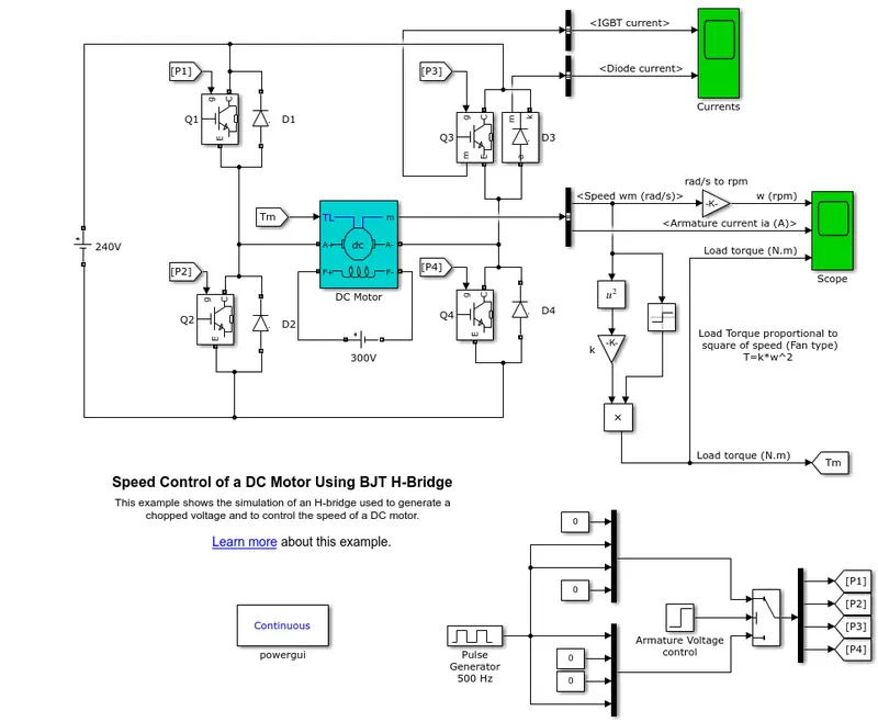
The Bipolar Junction Transistor (BJT) when used for power switching applications, operates as an IGBT. When it is conducting (BJT operating in the saturated region), a forward voltage Vf is developed between collector and emitter (in the range of 1 V). Therefore, the IGBT block can be used to model the BJT device.
The IGBT block does not simulate the gate current controlling the BJT or IGBT. The switch is controlled by a Simulink® signal (1/0). The DC motor uses the preset model (5 HP 24V 1750 rpm). It simulates a fan type load (where Load torque is proportional to square of speed). The armature mean voltage can be varied from 0 to 240 V when the duty cycle (specified in the Pulse Generator block) is varied from 0 to 100%.
The H-bridge consists of four BJT/Diode pairs (BJT simulated by IGBT models). Two transistors are switched simultaneously: Q1 and Q4 or Q2 and Q3. When Q1 and Q4 are fired, a positive voltage is applied to the motor and diodes D2-D3 operate as free-wheeling diodes when Q1 and Q4 are switched off. When Q2 and Q3 are fired, a negative voltage is applied to the motor and diodes D1-D4 operate as free-wheeling diodes when Q2 and Q3 are switched off.
HOW TO VARY SPEED IN DC MOTOR
We can control the speed of DC motor manually or through an automatic control device. This is different to speed regulation – where the speed can regulate against the natural change in speed due to a change in the load on the shaft.
The speed of a DC motor (N) is equal to
N = K (V – IaRa)/ ø Where, K is a constant
This implies three things:
- Speed of the motor is directly proportional to supply voltage.
- The Speed of the motor is inversely proportional to armature voltage drop.
- The motor speed is inversely proportional to the flux due to the field findings
Thus, the speed of a DC motor can control in three ways:
- By varying the flux, and by varying the current through field winding
- By varying the armature voltage, and the armature resistance Through the supply voltage .
we have pluse generator used in the above model that is used to control armature voltage which in turn control the speed of the motor.
intially we run the simulation at defaulted parameters and lets see the results from the scoop.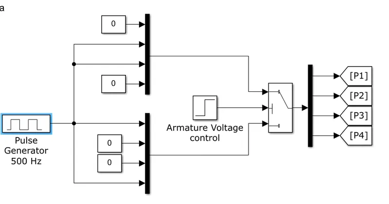
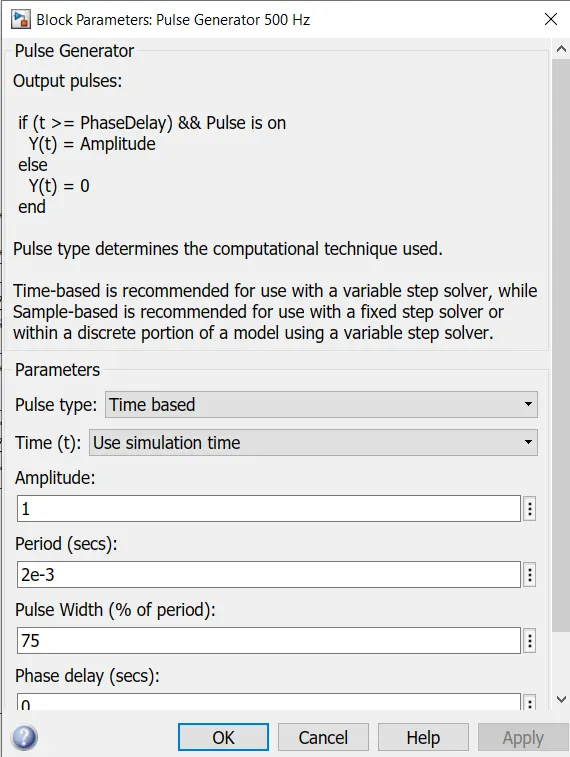
pulse generator:in this pulse generator we ahve implemented duty cycle in whic switch is on for 75% of time and off for the remaining %age.
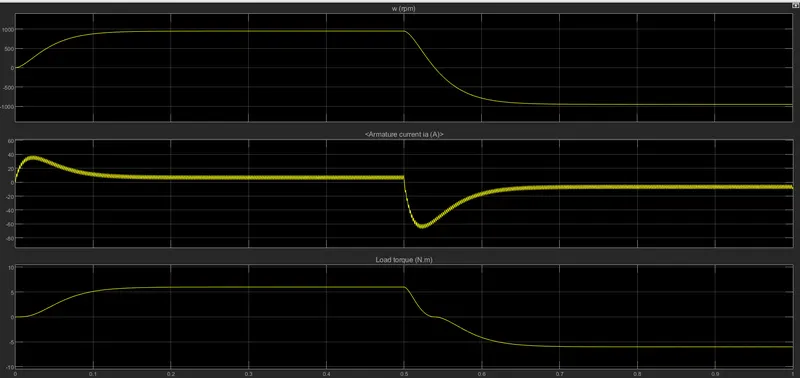
results from the above case:
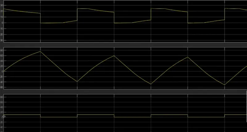
The motor starts in the positive direction with a duty cycle of 75% (mean DC voltage of 180V). At t= 0.5 sec., the armature voltage is suddenly reversed and the motor runs in the negative direction.
'Scope' shows motor speed, armature current and load torque and 'Currents' shows currents flowing in BJT Q3 and diode D3.
from current scoop we are going to see igbt current and diode current:
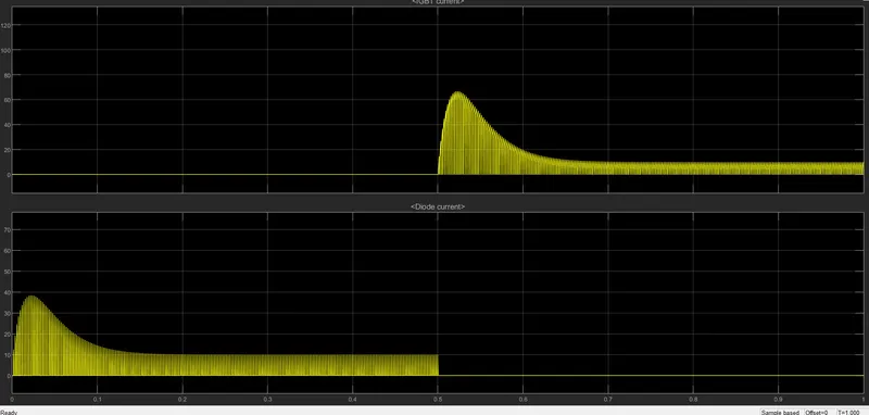
from the above result we have seen reducing voltage by implementing duty cycle reduces the voltage ,current which in turn reduces the speed of the motor.
if the supply voltage is further reduced to 50% (providing 120v out of 240v ) by implementing the duty cycle thsi ewill affect the motor speed again
50% duty cycle results will be shown below
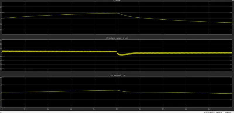
from the results its clear with in decrease in duty cycle it is going to affect the speed ,load torque and armature current.
Refer to the help section of ‘The Four-Quadrant Chopper DC Drive (DC7) block’. Compare it with the H-bridge model:
The Four-Quadrant Chopper DC Drive (DC7) block represents a four-quadrant, DC-supplied, chopper (or DC-DC PWM converter) drive for DC motors. This drive features closed-loop speed control with four-quadrant operation. The speed control loop outputs the reference armature current of the machine. Using a PI current controller, the chopper duty cycle corresponding to the commanded armature current is derived. This duty cycle is then compared with a sawtooth carrier signal to obtain the required PWM signals for the chopper.
The main advantage of this drive, compared with other DC drives, is that it can operate in all four quadrants (forward motoring, reverse regeneration, reverse motoring, and forward regeneration). In addition, due to the use of high switching frequency DC-DC converters, a lower armature current ripple (compared with thyristor-based DC drives) is obtained. However, four switching devices are required, which increases the complexity of the drive system.
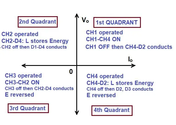
Type E or the fourth quadrant chopper consists of four semiconductor switches and four diodes arranged in antiparallel. The 4 choppers are numbered according to which quadrant they belong. Their operation will be in each quadrant and the corresponding chopper only be active in its quadrant.
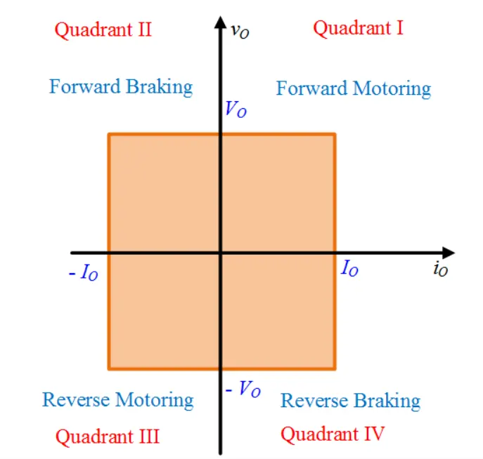
First quadrant operation:
CH4 is kept on and CH3 is kept off and CH1 is operated .when both CH1 and CH2 is operating simultaneously, the load gets directly connected to the source and hence the output voltage becomes equal to source voltage Vs=V0 and current Io(load current ) is going to flow from source to load in the direction shown in the figure
When CH1 is switched OFF, the load current freewheels through CH4 and D2. During this period, the load voltage and current remain positive.Thus, both the output voltage vs and load current io are positive and hence, the operation of chopper is in first quadrant. It may be noted that, Class-E chopper operates as a step-down chopper in this case.
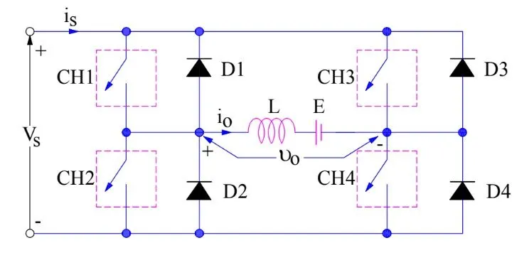
Second Quadrant Operation:
To obtain second quadrant operation, CH2 is operated while keeping the CH1, CH3 & CH4 OFF. When CH2 is ON, the DC source in the load drives current through CH2, D4, E and L. Inductor L stores energy during the On period of CH2.
When CH2 is turned OFF, the current is fed back to the source through D1, D4. It should be noted at this point that (E+Ldi/dt) is more than the source voltage Vs. As load voltage Vo is positive and Io is negative, it is the second quadrant operation of the chopper. Since the current is fed back to the source, this simply means that load is transferring power to the source.
For the second quadrant operation, load must contain emf E as shown in the circuit diagram. In the second quadrant, the configuration operates as a step-up chopper.
Third quadrent operation:
To obtain third quadrant operation, both the load voltage and load current should be negative. The current and voltage are assumed positive if their direction matches with what shown in the circuit diagram. If the direction is opposite to what shown in the circuit diagram, it is considered negative. One important thing to notice is that the polarity of emf E in load must be reversed to have third quadrant operation. Circuit diagram of Class-E chopper for third quadrant operation is shown below.
For third quadrant operation, CH1 is kept off, CH2 is kept ON and CH3 is operated. When CH3 is ON, load gets connected to source and hence load voltage is equal to source voltage. But carefully observe that the polarity of load voltage vo is opposite to what shown in the circuit diagram. Hence, vo is assumed negative. Let us now see what is the status of load current io. It may be seen that io is flowing in the direction opposite to shown in the circuit diagram and hence negative.
Now, when CH3 is turned OFF, the negative load current free wheels through the CH2 and D4. In this manner, vo and io both are negative. Hence, the chopper operates in third quadrant.
Fourth Quadrant Operation:
To obtain fourth quadrant operation, CH4 is operated while keeping CH1, CH2 and CH3 OFF. The polarity of load emf E needs to be reversed in this case too like third quadrant operation.
When CH4 is turned ON, positive current flows through CH4, D2, L and E. Inductance L stores energy during the time CH4 is ON. When CH4 is made OFF, current is fed back to the source through diodes D2, D3. Here load voltage is negative but the load current is always positive. This leads to chopper operation in fourth quadrant. Here, power is fed back to the source from load and chopper acts as a step-up chopper.
Comparision between h-bridge and four quadrent chopper
Four quadrent chopper can operate in all four quadrents /modes (forword motoring ,forword braking ,reverse motoring and reverse braking)
H-bridge can operate only in two modes forword and reverse
In 4 quadrent chopper regenerative braking is possible and this characteristic is not going to be seen in H-bridge.
In 4 quadrent chopper two pi regulator are used (speed regulator and current regulator )is used to obtain electromagnetic torque needed to reach the desired speed and control the armature current and stabilize the system but in H-bridge PI regulators are not going to use
4 quadrent chopper gives better efficiency and high energy storage as compared to H-bridge
MODULE 2#
EXPLAIN BLDC MOTOR:
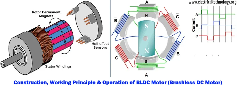
BLDC motor works on the principle similar to that of a Brushed DC motor. The Lorentz force law which states that whenever a current carrying conductor placed in a magnetic field it experiences a force. As a consequence of reaction force, the magnet will experience an equal and opposite force. In the BLDC motor, the current carrying conductor is stationary and the permanent magnet is moving.
When the stator coils get a supply from source, it becomes electromagnet and starts producing the uniform field in the air gap. Though the source of supply is DC, switching makes to generate an AC voltage waveform with trapezoidal shape. Due to the force of interaction between electromagnet stator and permanent magnet rotor, the rotor continues to rotate.
With the switching of windings as High and Low signals, corresponding winding energized as North and South poles. The permanent magnet rotor with North and South poles align with stator poles which causes the motor to rotate.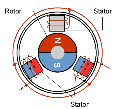
BELOW IS THE IMAGE OF BRUSHLESS DC MOTOR:
MODULE 3#
Develop a 2-quadrant chopper using simulink & explain the working of the same with the relevant results. (Refer to article - Multiquadrant operation of motor )
SIMULINK MODEL OF TYPE C CHOPPER AND HOW IT WORKS:
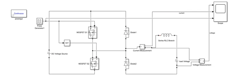
The Type – C chopper is a two quadrant chopper. In this chopper the output voltage is positive or zero whereas the output current can be either negative or positive.. For this model, the input supply is 24V; load consists of 1mH(1e^-3) inductance, and 12 V battery; and two MOSFET switches S1 and S2 and used along with two diodes as can be observed in the model The parameters set for the Gate Pulse block are as follows Amplitude-10, period -0.01s, pulsewidth-50%, and phase delay - 0 s
In this chopper when switch S1 is on current flows from source to load and when switch S2 is ON, current flows from load through switch S2. Thus load current can be positive or negative but load voltage remains positive. Switches S1 and S2 should not be turned on simultaneously as this would result in short circuit of the input supply. This chopper can be used for DC motor control and regenerative braking. The output voltage varies from 0V T0 24V. When the output current is positive, the power delivered to the load is positive and when the output current is negative, the power delivered to the load is negative.
RESULTS