Week-7 Challenge: DC Motor Control
Week-7 Challenge: DC Motor Control
1. A. Explain a MATLAB demo model named ‘Speed control of a DC motor using BJT H-bridge’.
B. Comment on the armature current shoot-up from the scope results.
C. Refer to the help section of ‘The Four-Quadrant Chopper DC Drive (DC7) block’. Compare it with the H-bridge model.
2. Develop a 2-quadrant chopper using Simulink & explain the working of the same with the relevant results. (Refer to the article - Multiquadrant operation of the motor )
3. Explain in a brief the operation of the BLDC motor.
Solution:
Open MATLAB demo model named ‘Speed control of a DC motor using BJT H-bridge’.
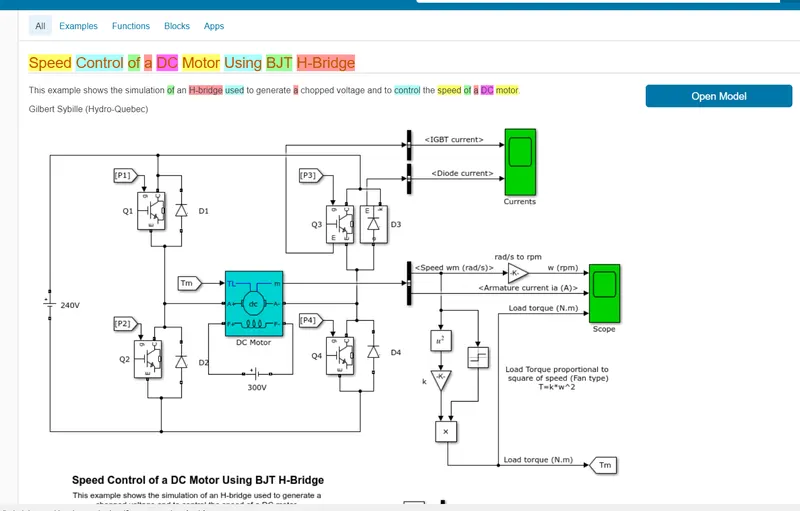
and Run the Model.
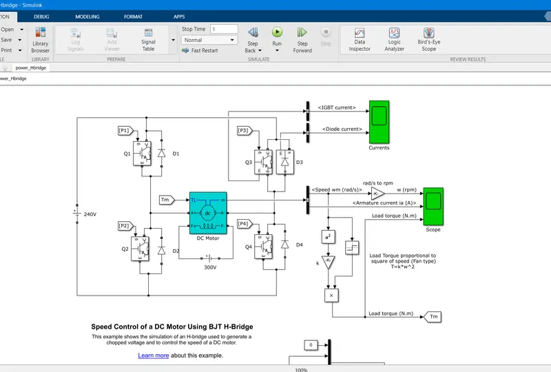
Comments:
This example shows the simulation of an H-bridge used to generate a chopped voltage and to control the speed of a DC motor.
In this model, a simple H-bridge is used to control the speed of the Motor.
H-bridge: It is the method of controlling the motor operation using the switching action of the switch at a certain switching frequency.
In this Model, IGBTs (Insulated-gate bipolar transistors) are used as a switch.
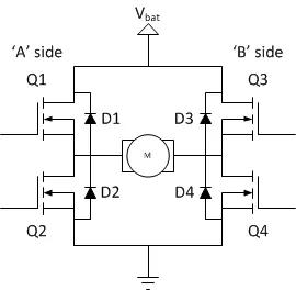
The switching elements (Q1..Q4) are usually bi-polar or FET transistors, in some high-voltage applications IGBTs. The diodes (D1..D4) are called catch diodes and are usually of a Schottky type.
The basic operating mode of an H-bridge:
Q1 and Q4 are turned on:

or Q2 and Q3 are turned on:

The direction of rotation will depend upon the mode of operation.
Description
The Bipolar Junction Transistor (BJT) when used for power switching applications, operates as an IGBT. When it is conducting (BJT operating in the saturated region), a forward voltage Vf is developed between collector and emitter (in the range of 1 V). Therefore, the IGBT block can be used to model the BJT device.
The IGBT block does not simulate the gate current controlling the BJT or IGBT. The switch is controlled by a Simulink® signal (1/0). The DC motor uses the preset model (5 HP 24V 1750 rpm). It simulates a fan type load (where Load torque is proportional to the square of speed). The armature means voltage can be varied from 0 to 240 V when the duty cycle (specified in the Pulse Generator block) is varied from 0 to 100%.
The H-bridge consists of four BJT/Diode pairs (BJT simulated by IGBT models). Two transistors are switched simultaneously: Q1 and Q4 or Q2 and Q3. When Q1 and Q4 are fired, a positive voltage is applied to the motor, and diodes D2-D3 operate as free-wheeling diodes when Q1 and Q4 are switched off. When Q2 and Q3 are fired, a negative voltage is applied to the motor, and diodes D1-D4 operate as free-wheeling diodes when Q2 and Q3 are switched off.
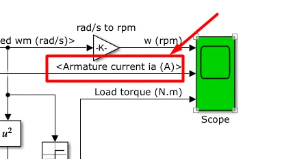
B. After the simulation is complete open the resulting scope as shown below.
Result:
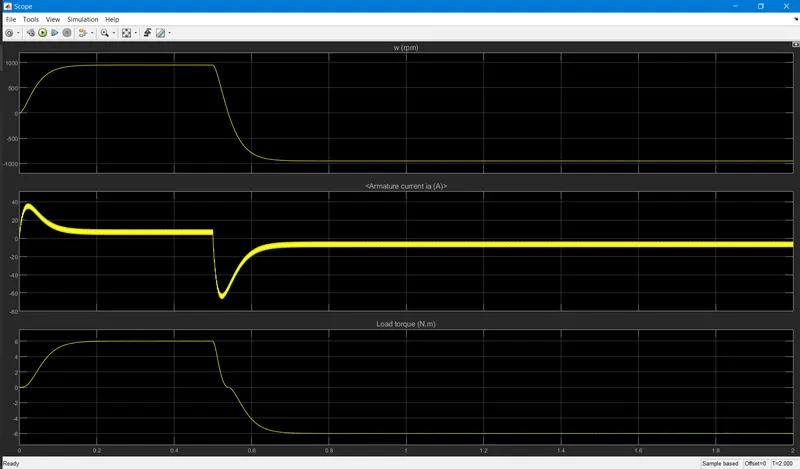
Check the Armature Curren Graph.
Simulation
The motor starts in the positive direction with a duty cycle of 75% (mean DC voltage of 180V). At t= 0.5 sec., the armature voltage is suddenly reversed and the motor runs in the negative direction.
Due to the sudden change in polarity of armature voltage this overshoot current appears in the graph because the motor windings are inductor type so due to armature inductance which tries to oppose the sudden change in current direction and tries to maintain the stable current level.
C. Refer to the help section of ‘The Four-Quadrant Chopper DC Drive (DC7) block’. Compare it with the H-bridge model.
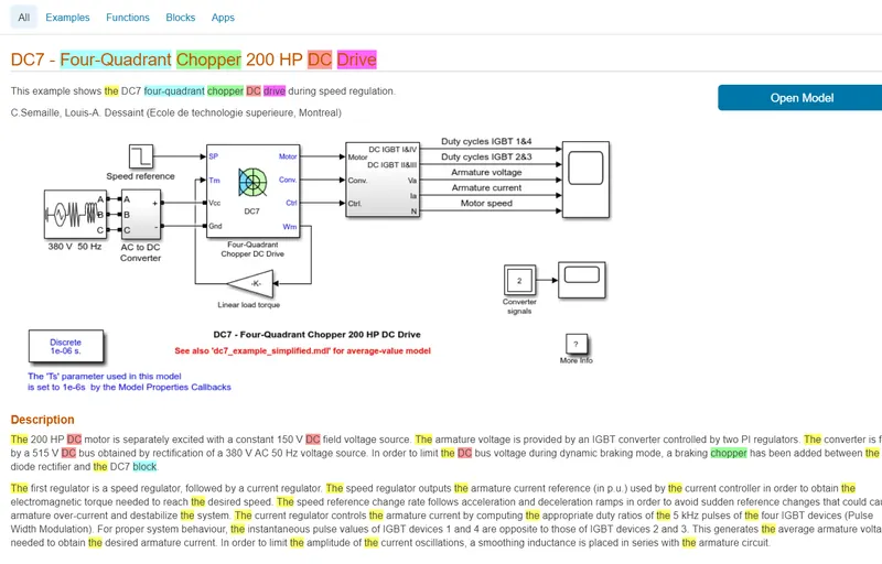
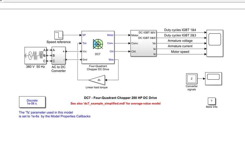
The Four-Quadrant Chopper DC Drive (DC7) block represents a four-quadrant, DC-supplied, chopper (or DC-DC PWM converter) drive for DC motors. This drive features closed-loop speed control with a four-quadrant operation. The speed control loop outputs the reference armature current of the machine.
Result:
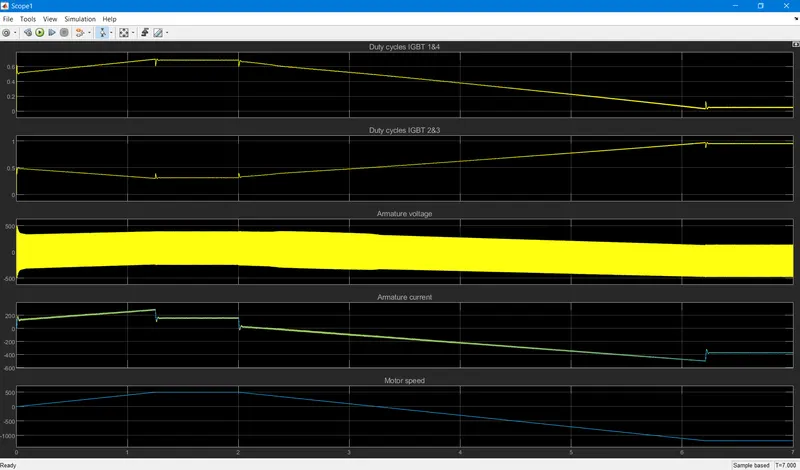
-Both models are almost similar but the advantage in using the Four-Quadrant model is we can operate the motor in all 4 quadrants of the graph
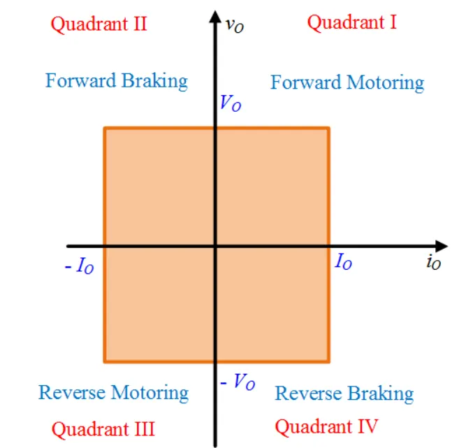
-The four-Quadrant model helped in preventing the Overshooting in armature Current. but in Hbridge we cannot prevent the overshooting in the armature current.
-Both Worked on the principal or switching action of the switch but the Four-Quadrant model provides more control and stable system.
-in the Four-Quadrant model regenerative breaking is possible but not in the H-bridge model.
2. Develop a 2-quadrant chopper using Simulink & explain the working of the same with the relevant results. (Refer to the article - Multiquadrant operation of the motor )
Solution:
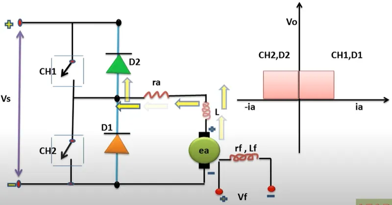
2-quadrant chopper
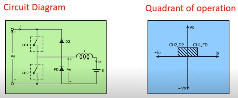
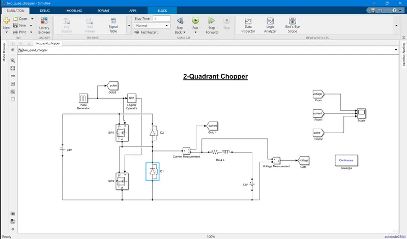
I am using MOSFET as a switch.
Components Required:
MOSFET as Switch, Diodes, Resistive & inductor load, voltage source, scope, pulse generator, logical NOT gate, voltage & current measurement block.
Circuit Diagram:
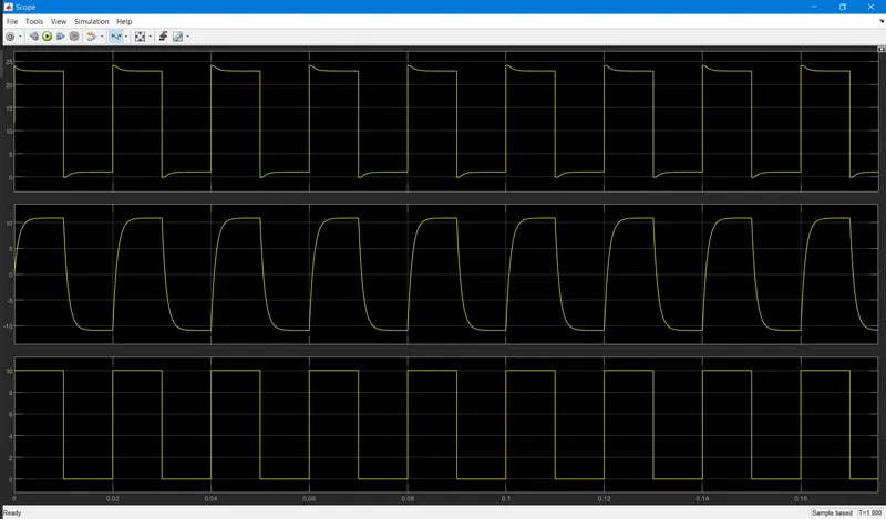
Result:
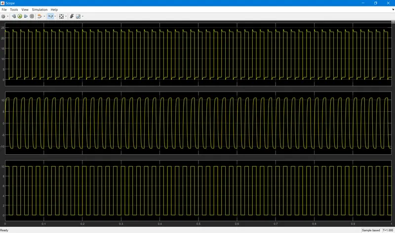
Zoomed Output:
Operation:
when the pulse is 1 then SW1 is SC and SW2 is OC.
then due to NOT gate when the pulse is 0 then SW2 is SC and SW1 is OC.
so at a time, only one SW is in operation. and I am Given the pulse duration is 50% means 50% duty cycle.
so for half cycle SW1 will operate and for the next half-cycle, SW2 will operate.
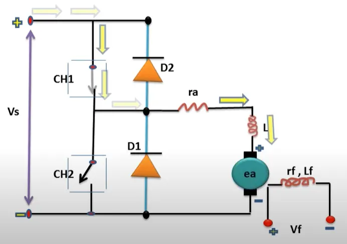
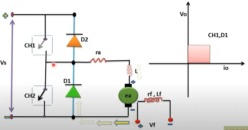
after SW1 is off then the inductor will dissipate its energy through D2.
in Regenerative braking mode. SW2 is ON and all the current will pass through SW2.
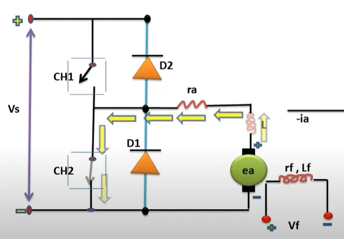
but after SW2 is off then all the armature current will pass through the D2 diode
Conclusion:
Motoring mode chopper drive offer first quadrant drive because its armature current and voltage remain +ve,
But regenerative braking offers a second quadrant drive its armature voltage to remain +ve and the armature current is revers.
In two-quadrant chopper drive both motoring mode and regenerative mode (two quadrant dc motor drive).
3. Explain in a brief, the operation of the BLDC motor.
Brushless DC electric motors are also known as electronically commutated motors (ECMs, EC motors). Primary efficiency is the most important feature for BLDC motors. Because the rotor is the sole bearer of the magnets and it doesn't require any power. i.e. no connections, no commutator, and no brushes. In place of these, the motor employs control circuitry. To detect where the rotor is at certain times, BLDC motors employ along with controllers, rotary encoders, or a Hall sensor.
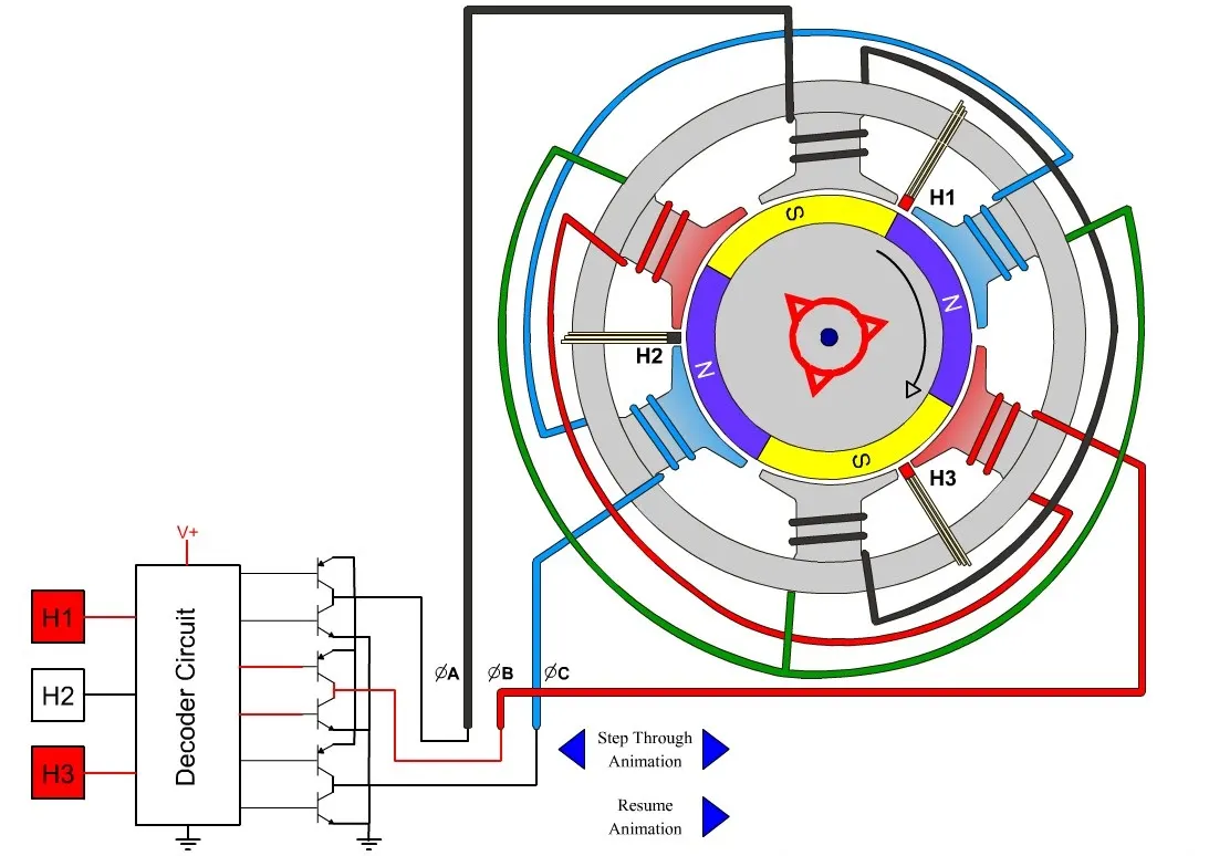
BLDC motor works on the principle similar to that of a Brushed DC motor. The Lorentz force law states that whenever a current-carrying conductor is placed in a magnetic field it experiences a force. As a consequence of the reaction force, the magnet will experience an equal and opposite force. In the BLDC motor, the current-carrying conductor is stationary and the permanent magnet is moving.
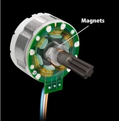
When the stator coils get a supply from the source, it becomes an electromagnet and starts producing the uniform field in the air gap. Though the source of supply is DC, switching makes to generates an AC voltage waveform with a trapezoidal shape. Due to the force of interaction between the electromagnet stator and permanent magnet rotor, the rotor continues to rotate.
With the switching of windings as High and Low signals, corresponding winding energized as North and South poles. The permanent magnet rotor with North and South poles aligns with stator poles which causes the motor to rotate.
-----------------------------------------------------------------------------------------------------------------------------------------------------------------------------------------------------------END---------------------------------------------------------------------------------------------------------------------------------------------------------------------------------------------