Project 1: Mini Project on Vehicle Direction Detection Using MATLAB-Simulink with Attachment of SLDD file and MBD SS.
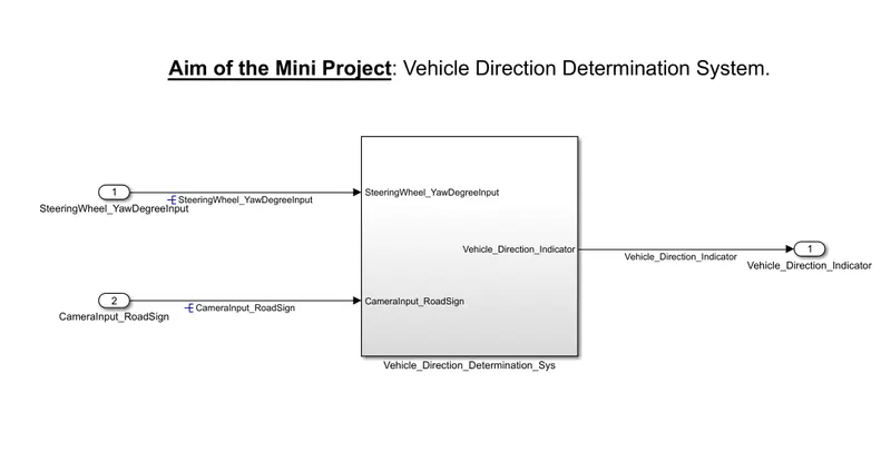
Aim of the Mini Project: Vehicle Direction Determination System.
Objective:
- Development of MATLAB Simulink model as per requirement.
- Tag the requirements to the Simulink model; tagging requirement 1 & requirement 2 to their corresponding subsystems is fine.
- MBD compliant changes, Data Dictionary creation & code generation is added advantage, and that is not the scope of this project.
- If choosing code generation, Storage class for Input signals: ImportedExtern; Storage class for Output signal: Export to File; Storage class for local signals: localizable; Storage class for calibration signals: Const.
- Choose sample time for all signals as 0.01s
Requirement - 1:
- Steering wheel input as yaw rate (Signal name: SteeringWheel_YawDegreeInput) is the input for this system.
- This is compared against 3 angular values, one each for a left turn, right turn & straight drive (Calibration Values: Right_Turn_AngularLimit, Left_Turn_AngularLimit, Straight_Drive_Steering_Angle) to say which specific direction the steering wheel is turning towards.
- Use switch blocks to compare & develop this requirement. Keep this requirement in a subsystem & the output of this requirement is a local signal (Signal Name: Vehicle_Turn_Status).
Requirement – 2:
- Keep this requirement as a separate subsystem. Inputs to this requirement are a local signal from requirement 1 (Signal Name: Vehicle_Turn_Status) & an input signal from the camera (Signal Name: CameraInput_RoadSign), which confirms the occurrence of a road sign.
- Signal Vehicle_Turn_Status is compared against calibration values (Calibration Values: RightTurn_RoadSign, LeftTurn_RoadSign, Straight_RoadSign), if each of them is found equal, then each of the three corresponding output is compared against the camera input signal,
- Using a logical operator block, only one among them is finally given as output signal (Signal Name: Vehicle_Direction_Indicator).
Signals & Calibration Data List:
|
Signal / Calibration Name |
Signal Type |
Data Type |
Dimension |
Min |
Max |
Initial Value |
Units |
|
SteeringWheel_YawDegreeInput |
Input |
Int16 |
1 |
-180 |
180 |
- |
Deg |
|
CameraInput_RoadSign |
Input |
Boolean |
1 |
0 |
1 |
- |
- |
|
Vehicle_Turn_Status |
Local |
Int16 |
1 |
-180 |
180 |
- |
Deg |
|
Right_Turn_AngularLimit |
Calibration |
Int16 |
[1 1] |
-180 |
180 |
30 |
Deg |
|
Left_Turn_AngularLimit |
Calibration |
Int16 |
[1 1] |
-180 |
180 |
-120 |
Deg |
|
Straight_Drive_Steering_Angle |
Calibration |
Int16 |
[1 1] |
-180 |
180 |
0 |
Deg |
|
RightTurn_RoadSign |
Calibration |
Int16 |
[1 1] |
-180 |
180 |
30 |
|
|
LeftTurn_RoadSign |
Calibration |
Int16 |
[1 1] |
-180 |
180 |
-120 |
|
|
Straight_RoadSign |
Calibration |
Int16 |
[1 1] |
-180 |
180 |
0 |
|
|
Vehicle_Direction_Indicator |
Output |
Boolean |
1 |
0 |
1 |
- |
- |
Solution:
For this Mini Project first, we have to develop the Simulink Model.
1st create a Main Subsystem name “Vehicle_Direction_Determination_Sys” having two inputs and one output.
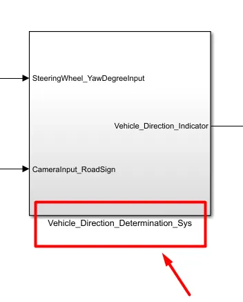
Input:
SteeringWheel_YawDegreeInput
CameraInput_RoadSign
Output:
Vehicle_Direction_Indicator
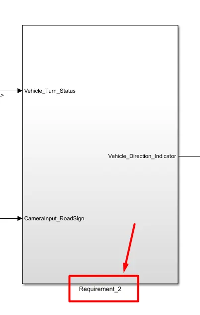
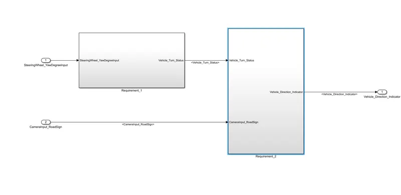
Inside the "Vehicle_Direction_Determination_Sys" make 2 subsystem name "Requirement_1" and "Requirement_2"
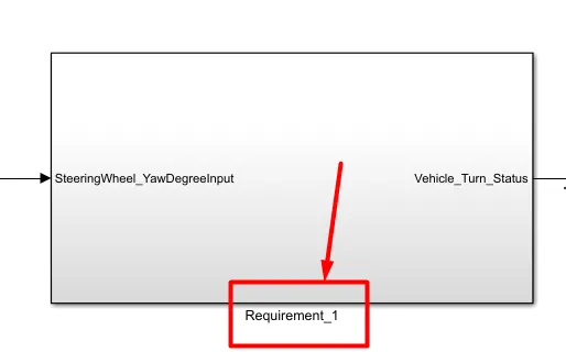
Requirement 1:
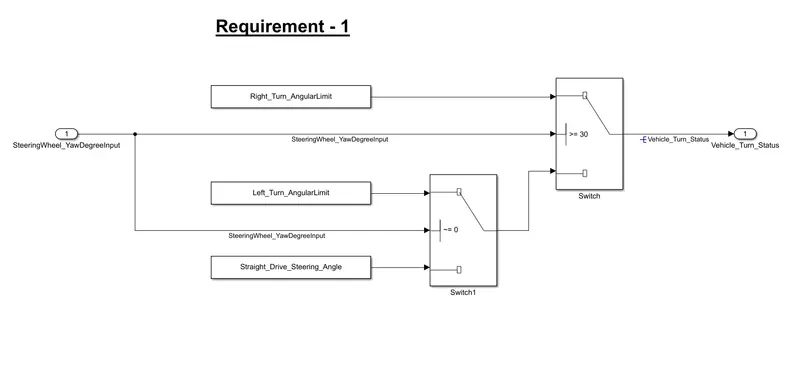
Inside the Requirement_1 Block as per the requirement, we have to create a logic:
- Steering wheel input as yaw rate (Signal name: SteeringWheel_YawDegreeInput) is the input for this system.
- This is compared against 3 angular values, one each for a left turn, right turn & straight drive (Calibration Values: Right_Turn_AngularLimit, Left_Turn_AngularLimit, Straight_Drive_Steering_Angle) to say which specific direction the steering wheel is turning towards.
- Use switch blocks to compare & develop this requirement. Keep this requirement in a subsystem & the output of this requirement is a local signal (Signal Name: Vehicle_Turn_Status).
Switch Block Working:
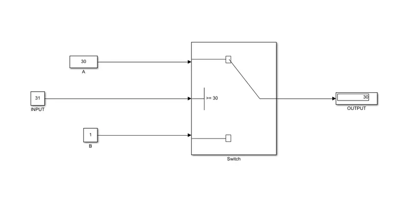
as you can see the switch block above, takes 3 inputs to give one compared output.
The main input is INPUT block and A, B for comparing with the condition of >=30. As the INPUT is 31 which satisfies the Block A condition then the OUTPUT is 30. And if the Block B Value
satisfies then the output is 1.
Simulink Block:
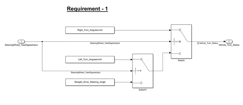
so,
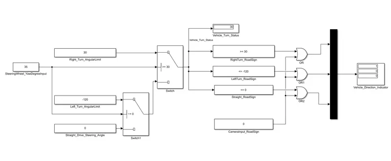
if SteeringWheel_YawDegreeInput satisfies the calibration value of Right_Turn_AngularLimit then the output is Right_Turn_AngularLimit,
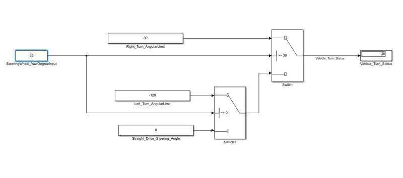
Fig. Testing of Right_Turn_AngularLimit condition.
else the output from Switch2,
Switch2 Condition:
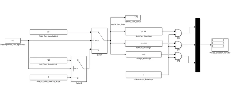
if SteeringWheel_YawDegreeInput satisfies the calibration value of Left_Turn_AngularLimit then the output is Left_Turn_AngularLimit,
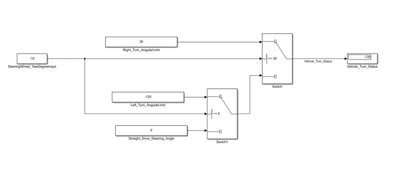
Fig. Testing of Left_Turn_AngularLimit condition.
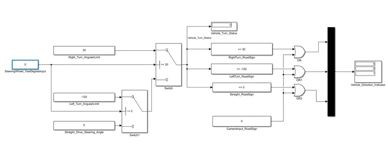
else the output is Straight_Drive_Steering_Angle.
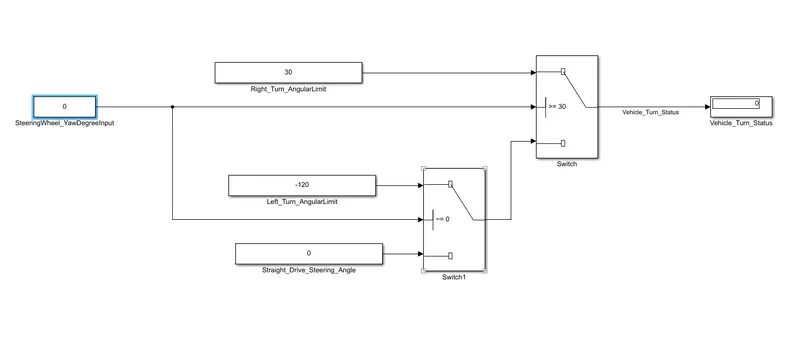
Fig. Testing of Straight_Drive_Steering_Angle condition.
Requirement 2:
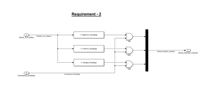
- Keep this requirement as a separate subsystem. Inputs to this requirement are a local signal from requirement 1 (Signal Name: Vehicle_Turn_Status) & an input signal from the camera (Signal Name: CameraInput_RoadSign), which confirms the occurrence of a road sign.
- Signal Vehicle_Turn_Status is compared against calibration values (Calibration Values: RightTurn_RoadSign, LeftTurn_RoadSign, Straight_RoadSign), if each of them is found equal, then each of the three corresponding output is compared against the camera input signal,
- Using a logical operator block, only one among them is finally given as output signal (Signal Name: Vehicle_Direction_Indicator).
for Requirement 2 we have to use OR logic because as truth table of OR Gate is if any of the conditions is true then the output is true.
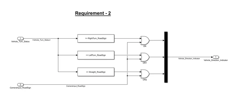
from Requirement 1's output Vehicle_Turn_Status is the input to Requirement 2.
so by the testing of condition, I Found that
Vehicle_Direction_Indicator is [ 1 0 0] for Right turn, the output is shown in the fig. below
Vehicle_Direction_Indicator is [ 0 1 0] for Left turn, the output is shown in the fig. below
Vehicle_Direction_Indicator is [ 0 0 1] for Straight movement, the output is shown in the fig. below
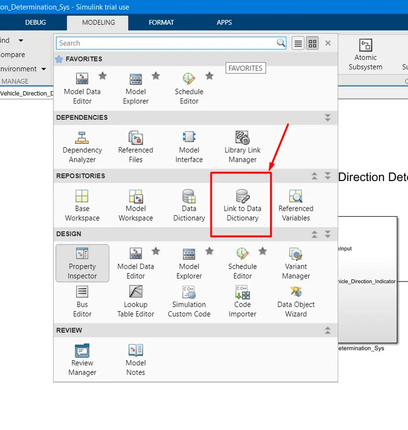
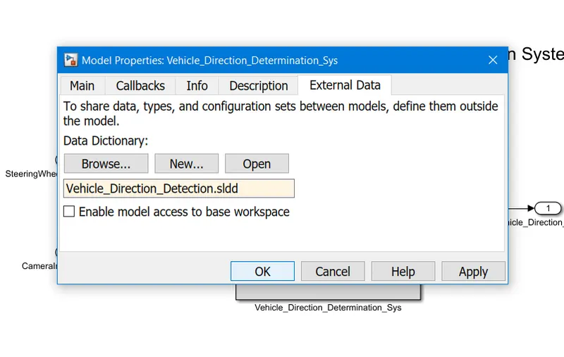
So After Successfully Creation of Model, we have to make SLDD (Simulink Data Dictionary) and attache to our model
for that goto Modelling >> Rerositories >> Link to Data Dictionary
Click on New and Name your SLDD file "Vehicle_Direction_Determination.sldd"
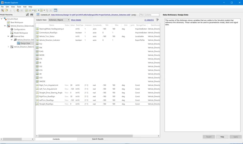
Signals & Calibration Data List:
|
Signal / Calibration Name |
Signal Type |
Data Type |
Dimension |
Min |
Max |
Initial Value |
Units |
|
SteeringWheel_YawDegreeInput |
Input |
Int16 |
1 |
-180 |
180 |
- |
Deg |
|
CameraInput_RoadSign |
Input |
Boolean |
1 |
0 |
1 |
- |
- |
|
Vehicle_Turn_Status |
Local |
Int16 |
1 |
-180 |
180 |
- |
Deg |
|
Right_Turn_AngularLimit |
Calibration |
Int16 |
[1 1] |
-180 |
180 |
30 |
Deg |
|
Left_Turn_AngularLimit |
Calibration |
Int16 |
[1 1] |
-180 |
180 |
-120 |
Deg |
|
Straight_Drive_Steering_Angle |
Calibration |
Int16 |
[1 1] |
-180 |
180 |
0 |
Deg |
|
RightTurn_RoadSign |
Calibration |
Int16 |
[1 1] |
-180 |
180 |
30 |
|
|
LeftTurn_RoadSign |
Calibration |
Int16 |
[1 1] |
-180 |
180 |
-120 |
|
|
Straight_RoadSign |
Calibration |
Int16 |
[1 1] |
-180 |
180 |
0 |
|
|
Vehicle_Direction_Indicator |
Output |
Boolean |
1 |
0 |
1 |
- |
- |
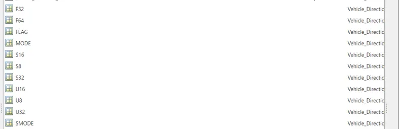
I also added the AliasType signal for different types of signals of uitn8, uint16, int8, int16, single, double, etc and stored them in a
Header file: standdard_defs.h
and after completing the SLDD data input the final settings:
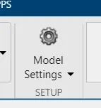
for that goto "Model Settings"
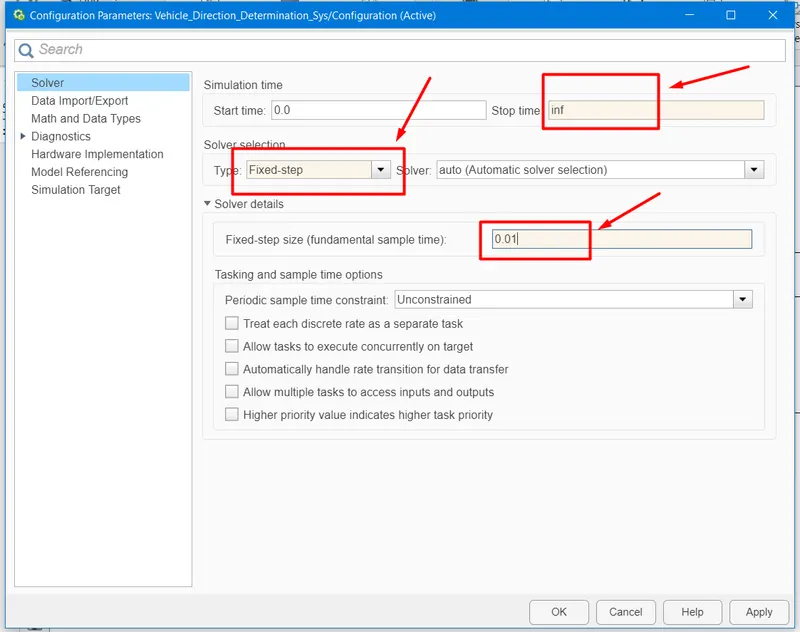
as data is given in requirements open solver:
change:
Solver Type to Fixed-step
sample time to 0.01
apply and ok/
Conclusion:
Hence the Vehicle Direction Determination System has been successfully designed in MATLAB Simulink and all the desired condition is fulfilled according to the requirements.