Week-7 Challenge: DC Motor Control
1. Explain a MATLAB demo model named ‘Speed control of a DC motor using BJT H-bridge’.
B. Comment on the armature current shoot-up from the scope results.
C. Refer to the help section of ‘The Four-Quadrant Chopper DC Drive (DC7) block’. Compare it with the H-bridge model.
AIM:
a. To explain about MATLAB demo model named ‘Speed control of a DC motor using BJT H-bridge’.
SIMULINK BLOCK OF SPEED CONTROL OF DC MOTOR USING BJT H-BRIDGE:
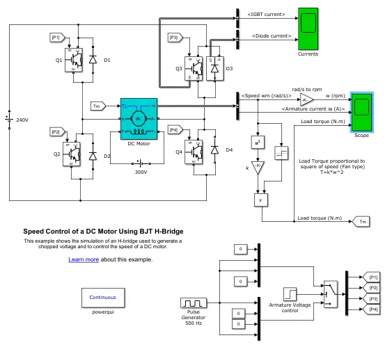
An H-bridge is a simple circuit that lets you control a DC motor to go backward or forward.
You normally use it with a microcontroller, such as an Arduino to control motors.
Concept of the H-bridge:
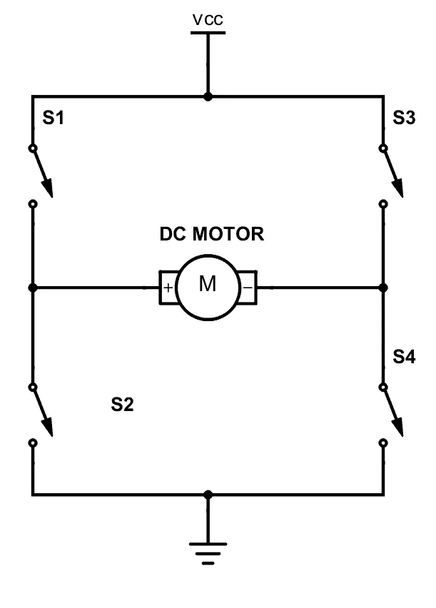
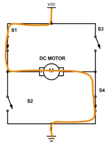
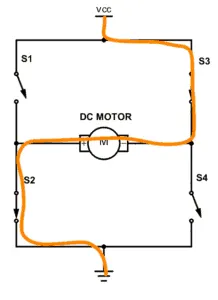
A DC motor spins either backward or forward, depending on how you connect the plus and the minus.
If you close switch 1 and 4, you have plus connected to the left side of the motor and minus to the other side. And the motor will start spinning in one direction.If you instead close switch 2 and 3, you have plus connected to the right side and minus to the left side. And the motor spins in the opposite direction.
H-bridge circuit:
From there you’ll learn that the transistor can work as a switch that you can open and close with the voltage on the base.
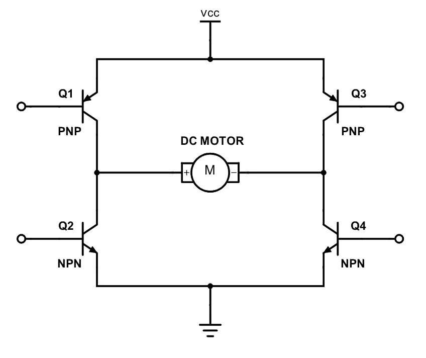
Since the transistor can be a switch, you’ll be able to make the motor spin in either direction by turning on and off the four transistors in the circuit above.
Usually, you control the transistors from a microcontroller.
The transistors you choose must:
- Handle enough current
- Use PNP (or pmos) at the top
- Have a low voltage drop between collector and emitter
The most important thing is that all the transistors can handle enough current for the motor. Otherwise it will burn out.
For example, if the motor draws 1 Ampere of current, you need transistors that can handle a minimum of 1 Ampere.
TRANSISTOR:
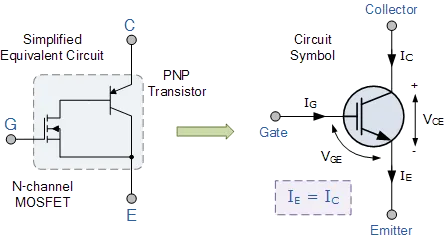
The IGBT is a power switching transistor which combines the advantages of MOSFETs and BJTs for use in power supply and motor control circuits
Insulated Gate Bipolar Transistor
IGBT Comparison Table
| Device Characteristic |
Power Bipolar |
Power MOSFET |
IGBT |
| Voltage Rating | High <1kV | High <1kV | Very High >1kV |
| Current Rating | High <500A | Low <200A | High >500A |
| Input Drive | Current, hFE 20-200 |
Voltage, VGS 3-10V |
Voltage, VGE 4-8V |
| Input Impedance | Low | High | High |
| Output Impedance | Low | Medium | Low |
| Switching Speed | Slow (uS) | Fast (nS) | Medium |
| Cost | Low | Medium | High |
We have seen that the Insulated Gate Bipolar Transistor is semiconductor switching device that has the output characteristics of a bipolar junction transistor, BJT, but is controlled like a metal oxide field effect transistor, MOSFET.
Because the IGBT is a voltage-controlled device, it only requires a small voltage on the Gate to maintain conduction through the device unlike BJT’s which require that the Base current is continuously supplied in a sufficient enough quantity to maintain saturation.
Also the IGBT is a unidirectional device, meaning it can only switch current in the “forward direction”, that is from Collector to Emitter unlike MOSFET’s which have bi-directional current switching capabilities (controlled in the forward direction and uncontrolled in the reverse direction).
The principal of operation and Gate drive circuits for the insulated gate bipolar transistor are very similar to that of the N-channel power MOSFET. The basic difference is that the resistance offered by the main conducting channel when current flows through the device in its “ON” state is very much smaller in the IGBT. Because of this, the current ratings are much higher when compared with an equivalent power MOSFET.
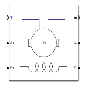
DC MOTOR USED:

b. Comment on the armature current shoot-up from the scope results.
RESULT:
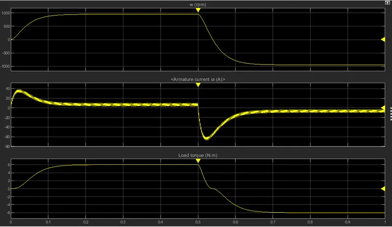
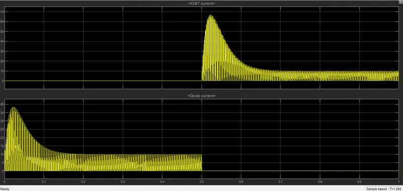
As observed from graph the armature,speed & load torque were high at initial 0-0.1 sec. From 0-0.5 sec the motor rotates in positive direction.Which the input pulse generator operating pulse width is @75%. So armature current leads to 38 A. This can be reduced by reducing the operating pulse width less than 75%.
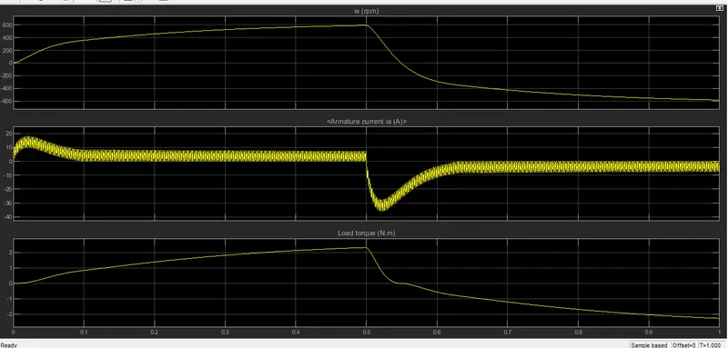
After 0.5sec the transistor swithing operation is performed & motor rotates in negative direction. This operation were carried by changing the transistor operating switched.
At 60% of pulse width
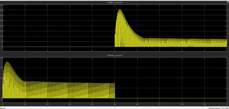
At 50% of pulse width
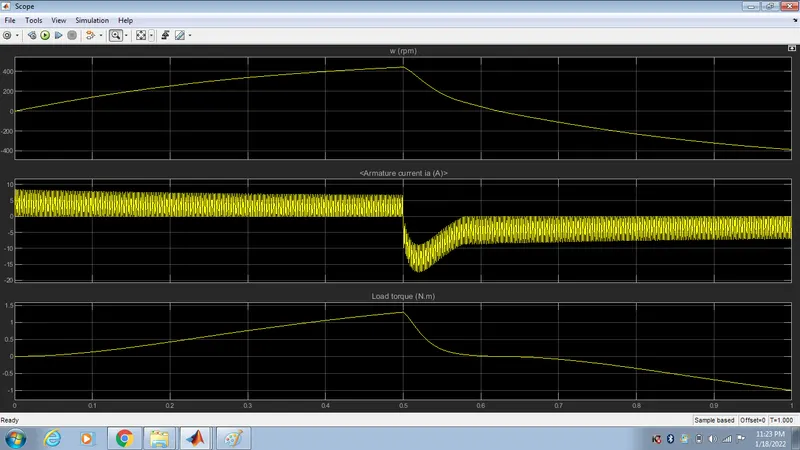
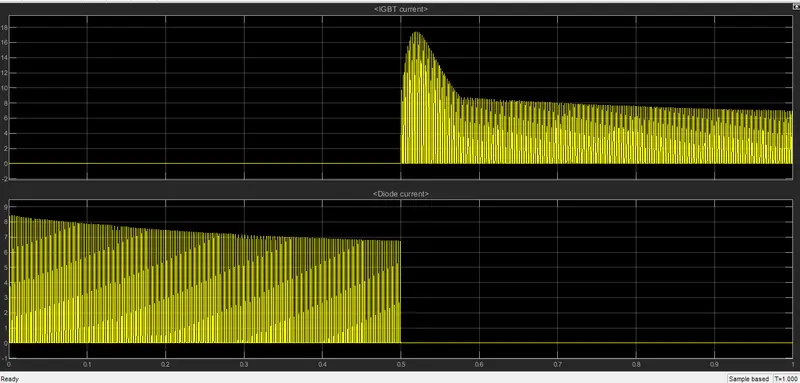
The switching operating current of armature were less when compare with 75%.
C. Refer to the help section of ‘The Four-Quadrant Chopper DC Drive (DC7) block’. Compare it with the H-bridge model.
SIMULINK MODEL:
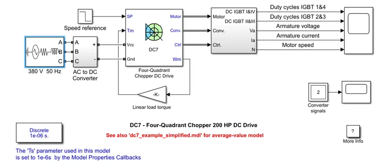
Four Quadrant Operation of any drives or DC Motor means that the machine operates in four quadrants. They are Forward Braking, Forward motoring, Reverse motoring and Reverse braking.
In motoring mode, the machine works as a motor and converts the electrical energy into mechanical energy, supporting its motion. In braking mode, the machine works as a generator and converts mechanical energy into electrical energy and as a result, it opposes the motion. The Motor can work in both, forward and reverse directions, i.e., in motoring and braking operations.
The product of angular speed and torque is equal to the power developed by a motor. For the multi-quadrant operation of drives, the following conventions about the signs of torque and speed are used. When the motor is rotated in the forward direction the speed of the motor is considered positive. The drives which operate only in one direction, forward speed will be their normal speed.
In loads involving up and down motions, the speed of the motor which causes upward motion is considered to be in forward motion. For reversible drives, forward speed is chosen arbitrarily. The rotation in the opposite direction gives reverse speed which is denoted by a negative sign.
The rate of change of speed positively in the forward direction or the torque which provides acceleration is known as Positive motor torque. In the case of retardation, the motor torque is considered negative. Load torque is opposite to the positive motor torque in the direction.
The figure below shows the four-quadrant operation of drives:
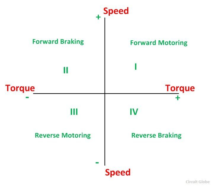
In the I quadrant power developed is positive and the machine is working as a motor supplying mechanical energy. The I (first) quadrant operation is called Forward Motoring.
II (second) quadrant operation is known as Braking. In this quadrant, the direction of rotation is positive, and the torque is negative, and thus, the machine operates as a generator developing a negative torque, which opposes the motion.
The kinetic energy of the rotating parts is available as electrical energy which may be supplied back to the mains. In dynamic braking, the energy is dissipated in the resistance.
The III (third) quadrant operation is known as the reverse motoring. The motor works, in the reverse direction. Both the speed and the torque have negative values while the power is positive.
In the IV (fourth) quadrant, the torque is positive, and the speed is negative. This quadrant corresponds to the braking in the reverse motoring mode.
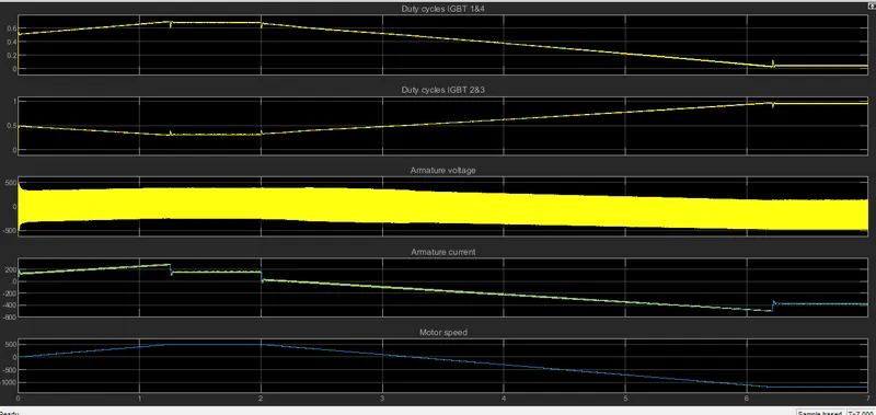
RESULT:
| FOUR QUDARANT CHOPPER | BJTH-BRIDGE | |
|
1. |
Four Quadrant chopper work in all four modes > Forward Motoring > Forward Braking > Reverse Motoring > Reverse Braking |
In h-bridge which operates onle in two modes > Forward Motoring > Reverse Motoring |
|
2. |
High switching frequency | Low switching frequency |
|
3. |
When transistor switching is done the armature current change over is has low spike | When transistor switching is done the armature current change over is has vey spike |
|
4. |
Which operated in DC voltage | Which operated in AC voltage |
|
5. |
Direction rotation of motor is switching the current signal get transisted from one to another | Direction rotation of motor is changed by polarity of current |
| 6. | Used in industrial application | Used in robotics application |
2.Develop a 2-quadrant chopper using simulink & explain the working of the same with the relevant results. (Refer to article - Multiquadrant operation of motor )
Two Quadrant chopper
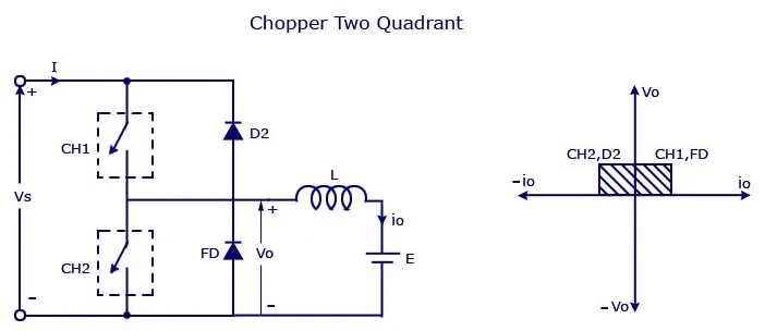
Type C chopper is obtained by connecting type –A and type –B choppers in parallel. We will always get a positive output voltage V0 as the freewheeling diode FD is present across the load. When the chopper is on the freewheeling diode starts conducting and the output voltage v0 will be equal to Vs . The direction of the load current i0 will be reversed. The current i0 will be flowing towards the source and it will be positive regardless the chopper is on or the FD conducts. The load current will be negative if the chopper is or the diode D2 conducts. We can say the chopper and FD operate together as type-A chopper in first quadrant. In the second quadrant, the chopper and D2 will operate together as type –B chopper.
The average voltage will be always positive but the average load current might be positive or negative. The power flow may be life the first quadrant operation ie from source to load or from load to source like the second quadrant operation. The two choppers should not be turned on simultaneously as the combined action my cause a short circuit in supply lines. For regenerative braking and motoring these type of chopper configuration is used.
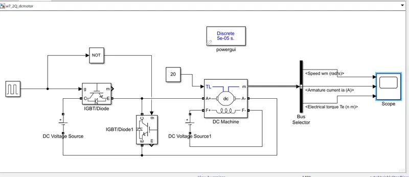
SIMULINK MODEl:
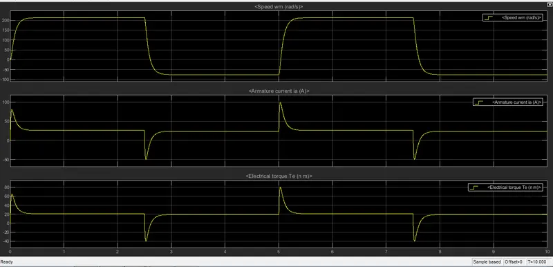
RESULT:
3.Explain in a brief about operation of BLDC motor.
INTRODUCTION:
A motor converts supplied electrical energy into mechanical energy. Various types of motors are in common use. Among these, brushless DC motors (BLDC) feature high efficiency and excellent controllability, and are widely used in many applications. The BLDC motor has power-saving advantages relative to other motor types.
Common Motor Types:
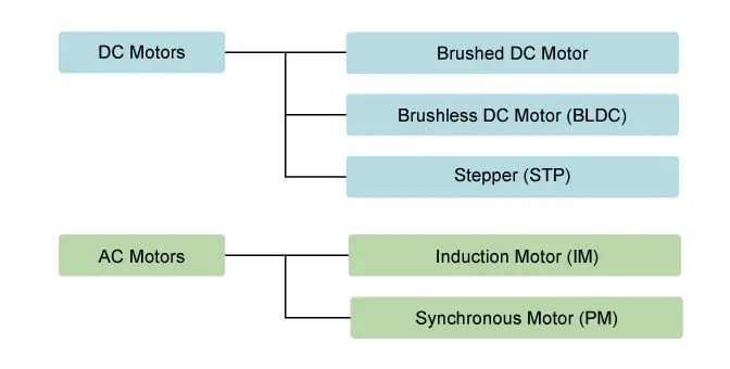
Motors differ according to their power type (AC or DC) and their method for generating rotation. Below, we look briefly at the features and uses of each type.
BRUSHLESS DC MOTOR:
As their name implies, brushless DC motors do not use brushes. With brushed motors, the brushes deliver current through the commutator into the coils on the rotor. So how does a brushless motor pass current to the rotor coils? It doesn’t—because the coils are not located on the rotor. Instead, the rotor is a permanent magnet; the coils do not rotate, but are instead fixed in place on the stator. Because the coils do not move, there is no need for brushes and a commutator.
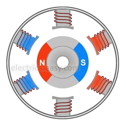
With the brushed motor, rotation is achieved by controlling the magnetic fields generated by the coils on the rotor, while the magnetic field generated by the stationary magnets remains fixed. To change the rotation speed, you change the voltage for the coils. With a BLDC motor, it is the permanent magnet that rotates; rotation is achieved by changing the direction of the magnetic fields generated by the surrounding stationary coils. To control the rotation, you adjust the magnitude and direction of the current into these coils.
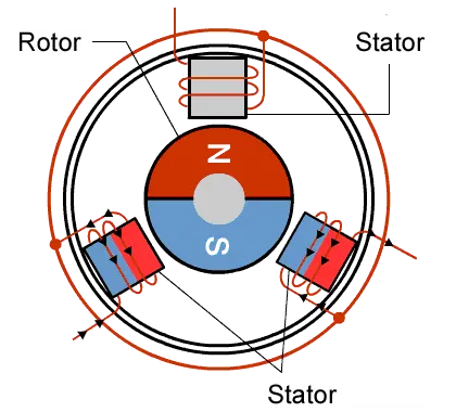
A BLDC Motor.
Since the rotor is a permanent magnet, it needs no current, eliminating the need for brushes and commutator. Current to the fixed coils is controlled from the outside.
Types of Brushless DC Motors
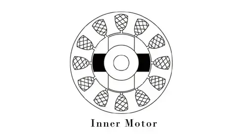
In an inner rotor design, the rotor is located in the centre of the motor and the stator winding surround the rotor. As the rotor is located in the core, rotor magnets do not insulate heat inside and heat get dissipated easily. Due to this reason, inner rotor designed motor produces a large amount of torque and validly used.
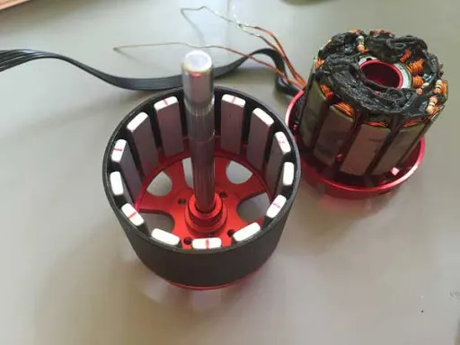
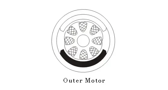
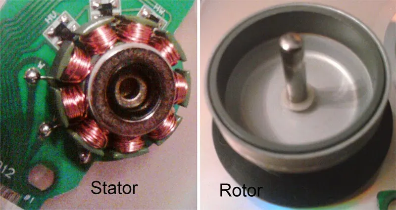
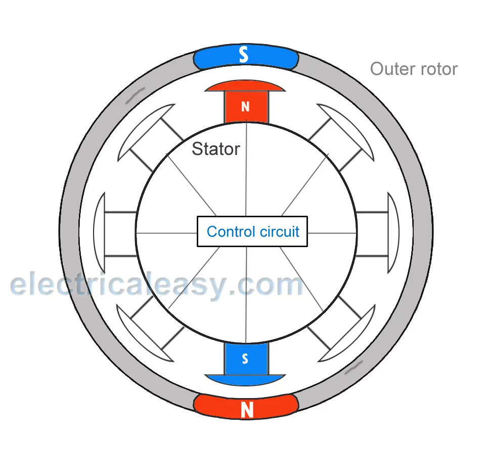
Outer Rotor Design:
Applications for BLDC Motors:
We’ve seen that BLDC motors offer high efficiency and controllability, and that they have a long operating life. Because of their efficiency and longevity, they are widely used in devices that run continuously. They have long been used in washing machines, air conditioners, and other consumer electronics and more recently, they are appearing in fans, where their high efficiency has contributed to a significant reduction in power consumption.
They are also being used to drive vacuum machines. In one case, a change in the control program resulted in a large jump in rotational speed an example of the superlative controllability offered by these motors.
BLDC motors are also being used to spin hard disc drives, where their durability keeps the drives operating dependably over the long term, while their power efficiency contributes to energy reduction in an area where this is becoming increasingly important.
The advantages of a BLDC motor:
- Brushless motors are more efficient as its velocity is determined by the frequency at which current is supplied, not the voltage.
- As brushes are absent, the mechanical energy loss due to friction is less which enhanced efficiency.
- BLDC motor can operate at high-speed under any condition.
- There is no sparking and much less noise during operation.
- More electromagnets could be used on the stator for more precise control.
- BLDC motors accelerate and decelerate easily as they are having low rotor inertia.
- It is high performance motor that provides large torque per cubic inch over a vast sped rang.
- BLDC motors do not have brushes which make it more reliable, high life expectancies, and maintenance free operation.
- There is no ionizing sparks from the commutator, and electromagnetic interference is also get reduced.
- Such motors cooled by conduction and no air flow are required for inside cooling.
The disadvantages of a BLDC motor:
- BLDC motor cost more than a brushed DC motor.
- The limited high power could be supplied to BLDC motor, otherwise, too much heat weakens the magnets and the insulation of winding may get damaged.
USAGES:
1.They will probably be widely used to drive service robots small robots that deliver services in fields other than manufacturing.
2. BLDC motors may also be replacing simple brushed dc motors in golf carts and mobility carts. In addition to their better efficiency, BLDC motors can also deliver more precise control which in turn can further extend battery life.
3. BLDC motors are also ideal for drones. Their ability to deliver precision control makes them especially suited for multirotor drones, where the drone’s attitude is controlled by precisely controlling the rotational speed of each rotor.