Week-7 Challenge: DC Motor Control
Aim :
1. A. Explain a MATLAB demo model named ‘Speed control of a DC motor using BJT H-bridge’.
B. Comment on the armature current shoot-up from the scope results.
C. Refer to the help section of ‘The Four-Quadrant Chopper DC Drive (DC7) block’. Compare it with the H-bridge model.
2. Develop a 2-quadrant chopper using simulink & explain the working of the same with the relevant results. (Refer to article - Multiquadrant operation of motor )
3. Explain in a brief about operation of BLDC motor.
Q.1 A :
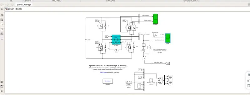
The bipolar junction (BJT) when used for power switching applications, operates as an IGBT. When Bjt is conducting ,a forward voltage VF is developed between collector and emittor in the range of 1v. Therefore IGBT can be used as BJT.
The IGBT does not simulate the gate current controlling the bjt or igbt. The switch is controlled by a simulink signal (1/0). The DC motor uses the preset mode (5Hp 24v 1750rpm).
It simulates a fan type load. where load torque is proporational to square of speed.
The armature mean voltage can be varied from 0 to 240 v when the duty cycle (specified in the pulse generator block) is varied from 0 to 100%.
The Hbridge consists of four bjt/diode pairs simulated by igbt models. Two transistors are switched simaltaneously : Q1and Q4 or Q2andQ3are fired.
A positive voltage is is applied to the motor and diodes D2-D3operates as free wheeling diodes when Q1andQ4 are switched off.
whenQ2andQ3 are fired, a negative voltage is applied to the motor and diodes D1D4 operates as free wheeling diodes when Q2 andQ3 are switched off.
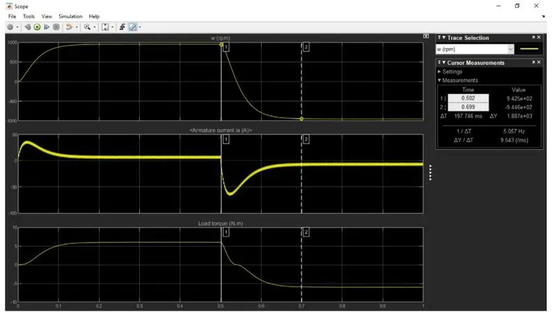
solution : The motor starts in the positive direction with a duty cycle of 75% (mean Dc voltage of 180v). at t= 0.5sec, the armature voltage is suddenly reversed and the motor runs in negative direction.
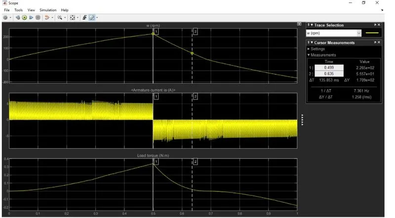
B. scope after runnig the default model after armature current shoot up
DC CHOORER CIRCUIT.
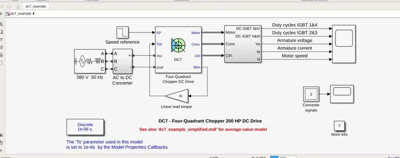
The 200HP DC motor is separetely excited with a constant 150v DC field voltage source. The armature voltage is provided by an igbt converter controlled by two pi regulators.
The convertors is fed by a 515v DC bus obtained by rectification of a 380V AC 50Hz voltage source.
IN order, to limit the DC bus voltage during Dynamic braking mode. Abraking chopper has been added between the diode rectifier and the DC & block.
The first regulator is a speed regulator, folllowed by a current regulator. Thespeed regulator outputs the armature current reference (in p.u) used by the current controller in order to obtain the electromagnetic torque needed to reach the desired spped.
The spped reference change rate follows acceleration and deceleration ramp in order to avoid sudden refernce changes that could cause armature over current and destablize the system.
The current regulator controls the armature current by computing the appropriate duty ratois of the 5kHz pulses of the four IGBT devices.
For proper system behaviour, the instataneous pulse values of IGBT devices 1 and 4 are opposite to those of IGBT devices 2 and 3. This generates the average armature voltage needed to obtain the desired armature current. IN order to limit the amplitude of the current oscillaions, a smoothing inductance is placed in series with the armature circuit.
H BRIDGE :
An H bridge is a simple circuit that lets you control a DC motor to go backward or forwaed.
If you close switch 1 and 4, you have plus connected to the left side of the motor and minus to the other side. and the motor will start spinning in one direction.
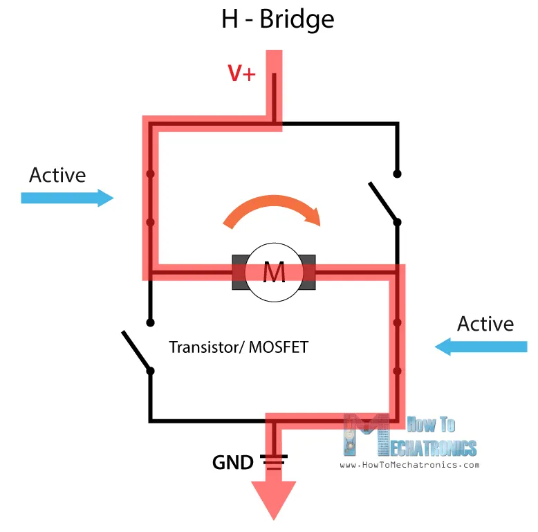
If you needed close switch 2 and 3 you have plis connected to the right side and minus to the left side and the motor spins in the opposite direction.