Week-7 Challenge: DC Motor Control
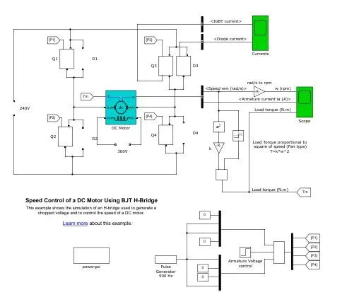
1. A. Explain a MATLAB demo model named ‘Speed control of a DC motor using BJT H-bridge’.
B. Comment on the armature current shoot-up from the scope results.
C. Refer to the help section of ‘The Four-Quadrant Chopper DC Drive (DC7) block’. Compare it with the H-bridge model.
The Bipolar Junction Transistor (BJT) when used for power switching applications, operates as an IGBT. When it is conducting (BJT operating in the saturated region), a forward voltage Vf is developed between collector and emitter (in the range of 1 V). Therefore, the IGBT block can be used to model the BJT device. The IGBT block does not simulate the gate current controlling the BJT or IGBT. The switch is controlled by a Simulink® signal (1/0). The DC motor uses the preset model (5 HP 24V 1750 rpm). It simulates a fan type load (where Load torque is proportional to square of speed). The armature mean voltage can be varied from 0 to 240 V when the duty cycle (specified in the Pulse Generator block) is varied from 0 to 100%. The H-bridge consists of four BJT/Diode pairs (BJT simulated by IGBT models). Two transistors are switched simultaneously: Q1 and Q4 or Q2 and Q3. When Q1 and Q4 are fired, a positive voltage is applied to the motor and diodes D2-D3 operate as free-wheeling diodes when Q1 and Q4 are switched off. When Q2 and Q3 are fired, a negative voltage is applied to the motor and diodes D1-D4 operate as free-wheeling diodes when Q2 and Q3 are switched off.
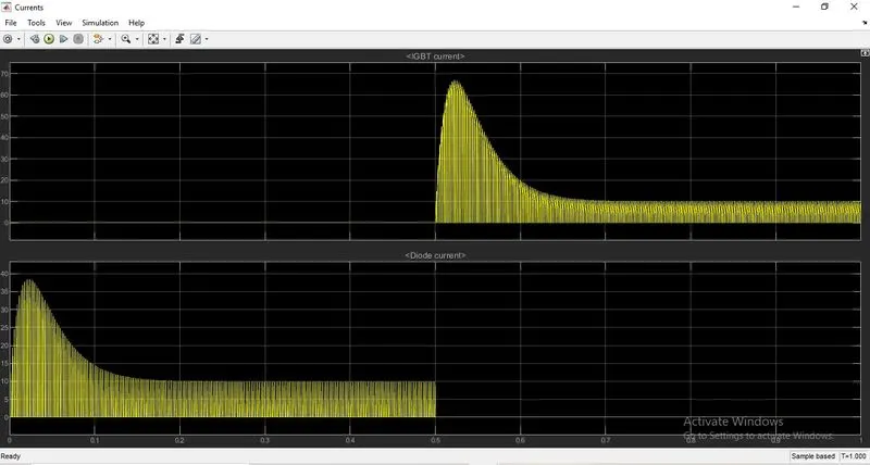
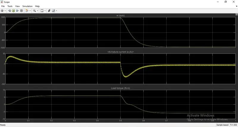
Here the figure shows the Motor torque, speed, and armature current. when the Duty cycle is in 75% the the armature current craetes a sudden down slope and reaches the negative cycle. At the time of slope we can see the speed and load troque are reduced and starts to operate in reverse direction.In this the motor operation wont be smooth and it will create a jerk which affects the motor.
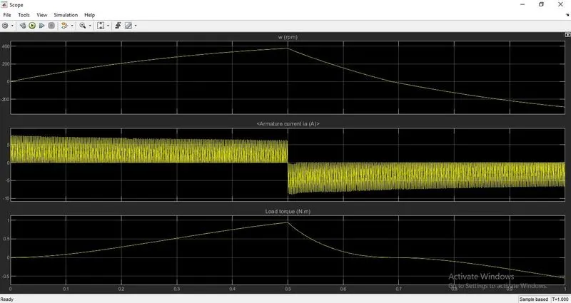
In the above graph we changed the duty cycle to 45%, so the the direction change will be smooth and if the motor motor speed is low than 75% duty cycle. if still the duty cycle is reduced the direction change will be even more smoother.
C. Refer to the help section of ‘The Four-Quadrant Chopper DC Drive (DC7) block’. Compare it with the H-bridge model.
Four modes-
forward motoring
forward breaking
reverse motoring
reverse breaking
BJT h bridge model works on two modes-
forward motoring
reverse motoring
* To change the direction of rotation of motor from forward to reverse and vice versa , the current signals get transited from one to other switch and in h bridge model, the direction of rotation of motor is changed by changing the polarity of current.
* The 4 quadrant chopper have high switching frequency and h bridge model have low switching frequency
* The armature current in 4 quadrant chopper have a little spike at transition from one to other switch because of high swithing frequency and h bridge model have high spike of current.
2. Develop a 2-quadrant chopper using simulink & explain the working of the same with the relevant results. (Refer to article - Multiquadrant operation of motor )
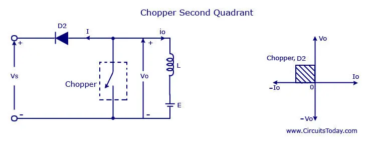
The second quadrant chopper the load must always contain a dc source E . When the chopper is on, v0 is zero but the load voltage E drives the current through the inductor L and the chopper, L stores the energy during the time Ton of the chopper . When the chopper is off , v0 =( E+ L . di/dt ) will be more than the source voltage Vs . Because of this the diode D2 will be forward biased and begins conducting and hence the power starts flowing to the source. No matter the chopper is on or off the current I0 will be flowing out of the load and is treated negative . Since VO is positive and the current I0 is negative , the direction of power flow will be from load to source. The load voltage V0 = (E+L .di/dt ) will be more than the voltage Vs so the type B chopper is also known as a step up chopper .
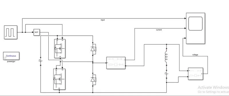
Here we giving an input of 12v with 50% duty cycle. There are current and voltage measurement block to measure the output of chopper.
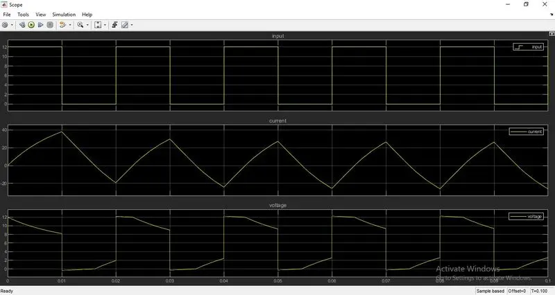
Result-
In this graph we can able to observe that the chopper chops an part of input voltage with respect to current and when the current is at max level there will be voltage drop at the same time there will be voltage rise when the current is near zero.
3. Explain in a brief about operation of BLDC motor.
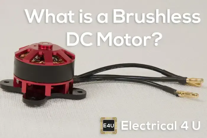
A brushless DC motor (also known as a BLDC motor or BL motor) is an electronically commuted dc motor which does not have brushes. The controller provides pulses of current to the motor windings which control the speed and torque of the synchronous motor
These types of motors are highly efficient in producing a large amount of torque over a vast speed range. In brushless motors, permanent magnets rotate around a fixed armature and overcome the problem of connecting current to the armature. Commutation with electronics has a large scope of capabilities and flexibility. They are known for smooth operation and holding torque when stationary.
Working principle
BLDC motor works on the principle similar to that of a conventional DC motor, i.e., the Lorentz force law which states that whenever a current carrying conductor placed in a magnetic field it experiences a force. As a consequence of reaction force, the magnet will experience an equal and opposite force. In case BLDC motor, the current carrying conductor is stationary while the permanent magnet moves.
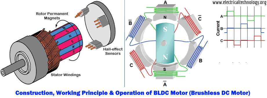
When the stator coils are electrically switched by a supply source, it becomes electromagnet and starts producing the uniform field in the air gap. Though the source of supply is DC, switching makes to generate an AC voltage waveform with trapezoidal shape. Due to the force of interaction between electromagnet stator and permanent magnet rotor, the rotor continues to rotate.
Consider the figure below in which motor stator is excited based on different switching states. With the switching of windings as High and Low signals, corresponding winding energized as North and South poles. The permanent magnet rotor with North and South poles align with stator poles causing motor to rotate.
Observe that motor produces torque because of the development of attraction forces (when North-South or South-North alignment) and repulsion forces (when North-North or South-South alignment). By this way motor moves in a clockwise direction.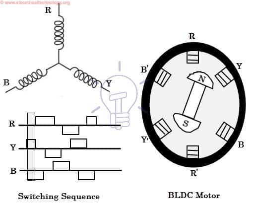
Here, one might get a question that how we know which stator coil should be energized and when to do. This is because; the motor continuous rotation depends on the switching sequence around the coils. As discussed above that Hall sensors give shaft position feedback to the electronic controller unit.
Based on this signal from sensor, the controller decides particular coils to energize. Hall-effect sensors generate Low and High level signals whenever rotor poles pass near to it. These signals determine the position of the shaft.
Brushless DC Motor Drive
As described above that the electronic controller circuit energizes appropriate motor winding by turning transistor or other solid state switches to rotate the motor continuously. The figure below shows the simple BLDC motor drive circuit which consists of MOSFET bridge (also called as inverter bridge), electronic controller, hall effect sensor and BLDC motor.
Here, Hall-effect sensors are used for position and speed feedback. The electronic controller can be a microcontroller unit or microprocessor or DSP processor or FPGA unit or any other controller. This controller receives these signals, processes them and sends the control signals to the MOSFET driver circuit.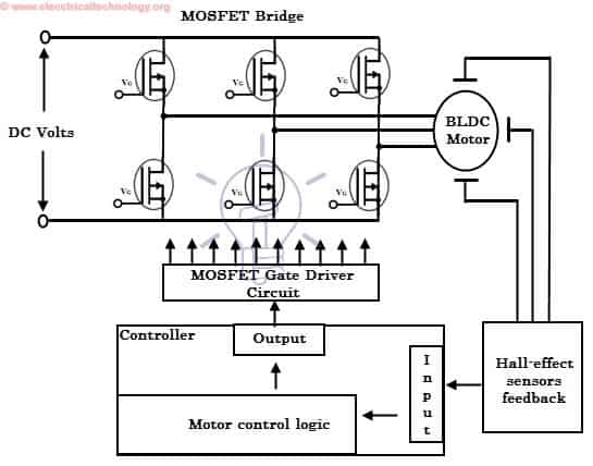
In addition to the switching for a rated speed of the motor, additional electronic circuitry changes the motor speed based on required application. These speed control units are generally implemented with PID controllers to have precise control. It is also possible to produce four-quadrant operation from the motor whilst maintaining good efficiency throughout the speed variations using modern drives.
Types of Brushless DC Motors
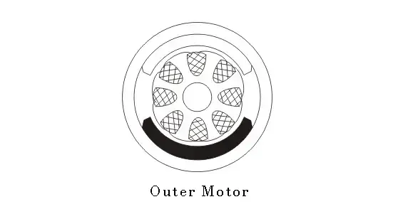
Basically, BLDC are of two types, one is outer rotor motor and other is inner rotor motor. The basic difference between the two is only in designing, their working principles are same.
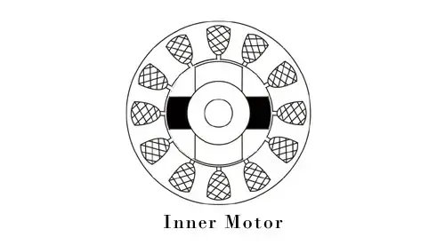
Inner Rotor Design
In an inner rotor design, the rotor is located in the centre of the motor and the stator winding surround the rotor. As the rotor is located in the core, rotor magnets do not insulate heat inside and heat get dissipated easily. Due to this reason, inner rotor designed motor produces a large amount of torque and validly used.
Outer Rotor Design
In outer rotor design, the rotor surrounds the winding which is located in the core of the motor. The magnets in the rotor trap the heat of the motor inside and do not allow to dissipate from the motor. Such type of designed motor operates at lower rated current and has low cogging torque.
Advantages of Brushless DC Motor
- Brushless motors are more efficient as its velocity is determined by the frequency at which current is supplied, not the voltage.
- As brushes are absent, the mechanical energy loss due to friction is less which enhanced efficiency.
- BLDC motor can operate at high-speed under any condition.
- There is no sparking and much less noise during operation.
- More electromagnets could be used on the stator for more precise control.
- BLDC motors accelerate and decelerate easily as they are having low rotor inertia.
- It is high performance motor that provides large torque per cubic inch over a vast sped rang.
- BLDC motors do not have brushes which make it more reliable, high life expectancies, and maintenance free operation.
- There is no ionizing sparks from the commutator, and electromagnetic interference is also get reduced.
- Such motors cooled by conduction and no air flow are required for inside cooling.
Disadvantages of Brushless DC Motors
- BLDC motor cost more than a brushed DC motor.
- The limited high power could be supplied to BLDC motor, otherwise, too much heat weakens the magnets and the insulation of winding may get damaged.