Week-7 Challenge: DC Motor Control
1a.ans:
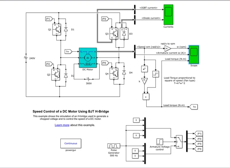
this model consists of a H bridge with 4 igbt - diode pair.the inputs such as duty cycle and step time are given from pulse generator block and armature voltage control block
- In general an H-bridge is a rather simple circuit, containing four switching element, with the load at the center, in an H-like configuration:
- The switching elements (Q1..Q4) are usually bi-polar or FET transistors, in some high-voltage applications IGBTs. Integrated solutions also exist but whether the switching elements are integrated with their control circuits or not is not relevant for the most part for this discussion. The diodes (D1..D4) are called catch diodes and are usually of a Schottky type.
- The top-end of the bridge is connected to a power supply (battery for example) and the bottom-end is grounded.
- In general all four switching elements can be turned on and off independently, though there are some obvious restrictions.
- Though the load can in theory be anything you want, by far the most pervasive application if H-bridges is with a brushed DC or bipolar stepper motor (steppers need two H-bridges per motor) load. In the following I will concentrate on applications as a brushed DC motor driver.
- Static Operation
- The basic operating mode of an H-bridge is fairly simple: if Q1 and Q4 are turned on, the left lead of the motor will be connected to the power supply, while the right lead is connected to ground. Current starts flowing through the motor which energizes the motor in (let’s say) the forward direction and the motor shaft starts spinning.
- If Q2 and Q3 are turned on, the reverse will happen, the motor gets energized in the reverse direction, and the shaft will start spinning backwards.
- In a bridge, you should never ever close both Q1 and Q2 (or Q3 and Q4) at the same time. If you did that, you just have created a really low-resistance path between power and GND, effectively short-circuiting your power supply. This condition is called ‘shoot-through’ and is an almost guaranteed way to quickly destroy your bridge, or something else in your circuit.
- Because of this restriction from the four possible states the side-A switches could be in only three make sense:
| Q1 | Q2 |
| open | open |
| close | open |
| open | close |
- Similarly for side-B:
| Q3 | Q4 |
| open | open |
| close | open |
| open | close |
- Altogether this allows for 9 different states for the full bridge to be in:
| Q1 | Q2 | Q3 | Q4 |
| close | open | open | open |
| close | open | open | close |
| close | open | close | open |
| open | close | open | open |
| open | close | open | close |
| open | close | close | open |
| open | open | open | open |
| open | open | open | close |
| open | open | close | open |
- We will get into much more detail in a minute, but before we do, let’s spend a few minutes understanding the basics of our load, the DC motor.
- Motor model
- While modeling DC motors is a complicated topic, one that you can read on extensively here, for this article, let’s just start with a very simple model! This model will not be useable for control applications, where you try to electrically compensate for the effects of mechanical components. The main assumption in the model introduced here is that the mechanical time-constants in your system are much higher than the electrical ones, in other words we can consider the shaft speed to be constant for our analysis. That’s true in almost all cases, but you’ll need to read other articels to understand why. For now, you’ll have to take my word for it.
- A DC motor is an energy conversion device: it takes electrical energy and turns it into mechanical energy. When operated as a generator, it does the opposite: converts mechanical energy into electrical.
- In this very simple motor model, the mechanical parameters are completely ignored. On the electrical side, the motor basically contains a number of inductors, that move in a magnetic field. The inductors themselves of course have an inductance, and some internal resistance. Their movement in the field will generate a voltage – called generator voltage and denoted by Vg – across the inductors. From this description, the following model can be drawn:
- In fact in many cases, the internal resistance of the inductors can be disregarded, and an even simpler model, an ideal inductor in series with a voltage source can be used:
- In both cases, all the elements are in series, so they share the same current, but the voltage across them of course is different.
- The generator voltage (Vg) depends only on the speed by which the inductors move in the field, in other words on the rotational speed of the motor.
- The force (or torque in a rotational system, like a DC motor) these electromagnets – inductors – exert is proportional to the current flowing through them.
- Drive modes
- Previously we’ve only considered static operation, when nothing was changing. If less than full-speed operation is intended the switches are controlled in a PWM fashion. A pwm signalhas two phases, the ‘on-time’ and the ‘off-time’ as I’m calling them in the diagram below:
- It is a periodic signal, with a constant frequency. The information content – that is used to change the operating parameters of the bridge – is the ratio between the on-time and the off-time. The various drive modes differ in how the switches are set during the on-time and the off-time.
- If we want the motor to do anything interesting, we will have to connect it to the power supply in at least one of the phases. Let’s say it is the ‘on-time’. We have two choices: either we turn on Q1 and Q4 or we turn on Q2 and Q3.
- But what about the off-time? We have nine states to chose from. These are:
| Q1 | Q2 | Q3 | Q4 |
| close | open | open | open |
| close | open | open | close |
| close | open | close | open |
| open | close | open | open |
| open | close | open | close |
| open | close | close | open |
| open | open | open | open |
| open | open | open | close |
| open | open | close | open |
- If you look back at our motor model, you’ll see that it’s basically an inductive load. Inductors have the property that you can’t change the current flowing through them instantaneously. So, whenever the bridge changes state with the motor current being non-zero, the new state has to make sure that the current can continue to flow in some way. The catch diodes are usually not used for this purpose, because (as you will see later) they would heat up too much. There are of course exceptions, but those are just that: exceptions.
- Now, during the on-time the motor inductor is connected between the power supply and GND. Consequently the current will start rising through the inductor. It is very unlikely that by the time the on-time is over, and we’re ready to switch the bridge into its off-time state, the current would be 0. So its best to choose a state for the off-time where we can provide a path for the inductor-current to flow. In order to do that, we’ll have to close one switch each on both sides of the motor, and that prunes out our possible off-time states quite a bit:
| Q1 | Q2 | Q3 | Q4 |
| close | open | open | close |
| close | open | close | open |
| open | close | open | close |
| open | close | close | open |
- If we combine those four choices with the two possible on-time states, we get eight possible configurations. In two of them however both the on-time and the off-time states are the same, and those are not terribly interesting: the bridge operates in a static way. That leaves us with six meaningful mappings, that I’ll summarize below:
| Mapping 1 | Q1 | Q2 | Q3 | Q4 |
| on-time state | close | open | open | close |
| off-time state | close | open | close | open |
| Mapping 2 | Q1 | Q2 | Q3 | Q4 |
| on-time state | close | open | open | close |
| off-time state | open | close | open | close |
| Mapping 3 | Q1 | Q2 | Q3 | Q4 |
| on-time state | close | open | open | close |
| off-time state | open | close | close | open |
| Mapping 4 | Q1 | Q2 | Q3 | Q4 |
| on-time state | open | close | close | open |
| off-time state | close | open | open | close |
| Mapping 5 | Q1 | Q2 | Q3 | Q4 |
| on-time state | open | close | close | open |
| off-time state | close | open | close | open |
| Mapping 6 | Q1 | Q2 | Q3 | Q4 |
| on-time state | open | close | close | open |
| off-time state | open | close | open | close |
- You can find some interesting symmetries in the tables.
- For example mapping 3 and 4 change both sides. However if we swap side-A and side-B in mapping 3, we get mapping 4, and vice versa. We call these mappings the ‘lock anti-phase drive’.
- The other four mappings (1, 2, 5 and 6) only change the state of one side of the bridge. Mapping 1 and 5 are however mirrors of each other the same way as 3 and 4 were: by swapping side-A and side-B we can transform one into the other. The same holds true for mapping 2 and 6. We call this type of operation the ‘phase-magnitude drive’.
- In future parts of the article, I’ll talk in detail about both drive modes.
- This simple categorization of drive modes works for most cases but not for all. There are some more esoteric drive modes that can be beneficial under certain rare circumstances.
b.ans:
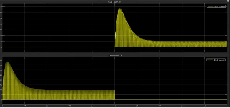
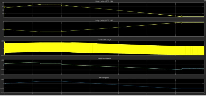
the above graphs shows the current passing through igbt and diode .so 0 to 0.5sec current is following
through the diode d3 and 0.5 to 1sec the current is passing through q3
here load torque is proportional to the square of angular velocity
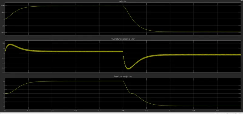
the above graph shows that the begining of the cycle there is a sudden peak in armature current bcz of when we start motor suddenly it take some time to get stable .in that time we get sudden peak.
c.ans:
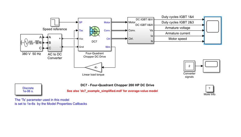
four quadrent chopeer:
1.regenerative braking is possible
2.the current values are chopped not continous hence simulation takes less time
3.widely used in auto mobiles to control dc motor speed and direction
4.to change to direction of motor current signals are interuped with one anouther
H-bridge:
1.regenerative braking is not posssible but dynamic braking can be acheived
2.the current values are continuos
3.widely used in robotics and electromechanical devices
4. to change the direction of motor only the polarity of the current is changed
2.ans:
Type -C chopper or Two-quadrant type-A Chopper:
Type C chopper is obtained by connecting type –A and type –B choppers in parallel. We will always get a positive output voltage V0 as the freewheeling diode FD is present across the load. When the chopper is on the freewheeling diode starts conducting and the output voltage v0 will be equal to Vs . The direction of the load current i0 will be reversed. The current i0 will be flowing towards the source and it will be positive regardless the chopper is on or the FD conducts. The load current will be negative if the chopper is or the diode D2 conducts. We can say the chopper and FD operate together as type-A chopper in first quadrant. In the second quadrant, the chopper and D2 will operate together as type –B chopper.
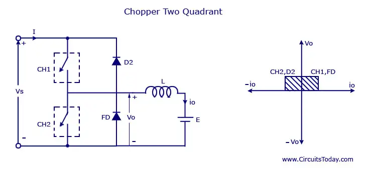
The average voltage will be always positive but the average load current might be positive or negative. The power flow may be life the first quadrant operation ie from source to load or from load to source like the second quadrant operation. The two choppers should not be turned on simultaneously as the combined action my cause a short circuit in supply lines. For regenerative braking and motoring these type of chopper configuration is used.
simulink model:
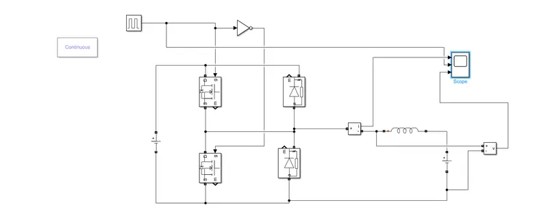
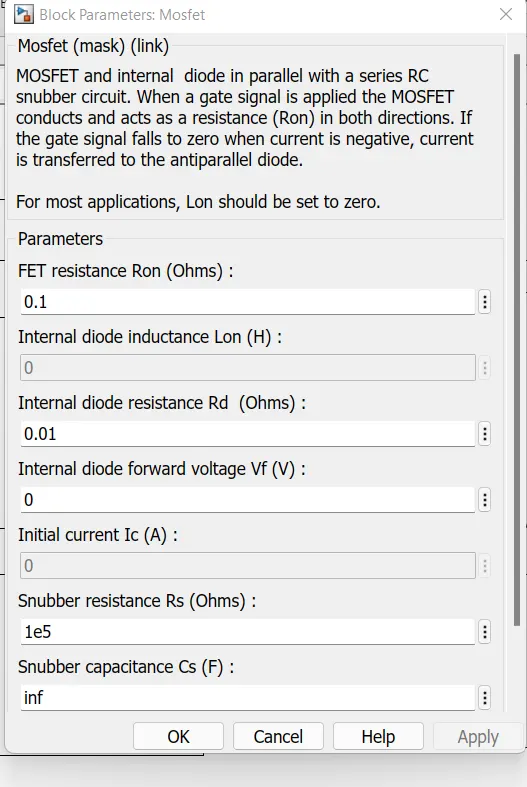
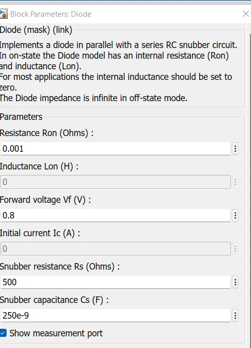
let us two mosfets blocks and diodes and connect it as shown in modeel apllying dc coltage 24v at input and at load is 12v
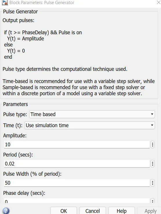
pulse generator:
mosfet:
diode:
scope results:
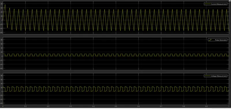
the voltage wave form is not going less than zero.the minmum value of voltage is zero and it is always in positiuve direction
however in current waveform,the current increases and decreases .
3.ans:
- Brushless DC Motors (BLDC):
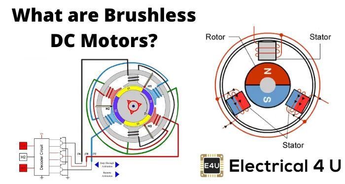
What is a Brushless Motor?
A brushless DC motor (also known as a BLDC motor or BL motor) is an electronically commuted dc motor which does not have brushes. The controller provides pulses of currentto the motor windings which control speed and torque of the synchronous motor.
These types of motors are highly efficient in producing a large amount of torque over a vast speed range. In brushless motors, permanent magnets rotate around a fixed armature and overcome the problem of connecting current to the armature. Commutation with electronics has a large scope of capabilities and flexibility. They are known for smooth operation and holding torque when stationary.
How Does a Brushless Motor Work
Before explaining the working of a brushless DC motor, it is better to understand the function of a brushed motor. In brushes motors, there are permanent magnets on the outside and a spinning armature which contains electromagnet is inside. These electromagnets create a magnetic feild
in the armature when the power is switched on and help to rotate the armature.
The brushes change the polarity of the pole to keep the rotation on of the armature. The basic working principle for the brushed DC motor and for brushless DC motor are same i.e. internal shaft position feedback.
Brushless DC motor has only two basic parts: rotor and the stator. The rotor is the rotating part and has rotor magnets whereas stator is the stationary part and contains stator windings. In BLDC permanent magnets are attached in the rotor and move the electromagnets to the stator. The high power transistors are used to activate electromagnets for the shaft turns. The controller performs power distribution by using a solid-state circuit.
Types of Brushless DC Motors
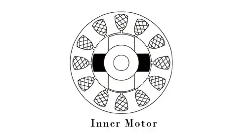
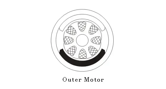
Basically, BLDC are of two types, one is outer rotor motor and other is inner rotor motor. The basic difference between the two is only in designing, their working principles are same.
Inner Rotor Design
In an inner rotor design, the rotor is located in the centre of the motor and the stator winding surround the rotor. As the rotor is located in the core, rotor magnets do not insulate heat inside and heat get dissipated easily. Due to this reason, inner rotor designed motor produces a large amount of torque and validly used.
Outer Rotor Design
In outer rotor design, the rotor surrounds the winding which is located in the core of the motor. The magnets in the rotor trap the heat of the motor inside and do not allow to dissipate from the motor. Such type of designed motor operates at lower rated current and has low cogging torque.
Advantages of Brushless DC Motor
The advantages of a BLDC motor are:
- Brushless motors are more efficient as its velocity is determined by the frequency at which current is supplied, not the voltage.
- As brushes are absent, the mechanical energy loss due to friction is less which enhanced efficiency.
- BLDC motor can operate at high-speed under any condition.
- There is no sparking and much less noise during operation.
- More electromagnets could be used on the stator for more precise control.
- BLDC motors accelerate and decelerate easily as they are having low rotor inertia.
- It is high performance motor that provides large torque per cubic inch over a vast sped rang.
- BLDC motors do not have brushes which make it more reliable, high life expectancies, and maintenance free operation.
- There is no ionizing sparks from the commutator, and electromagnetic interference is also get reduced.
- Such motors cooled by conduction and no air flow are required for inside cooling.
Disadvantages of Brushless DC Motors
The disadvantages of a BLDC motor are:
- BLDC motor cost more than a brushed DC motor.
- The limited high power could be supplied to BLDC motor, otherwise, too much heat weakens the magnets and the insulation of winding may get damaged.