Week-6 Challenge: EV Drivetrain
1.ans:
different types of power converter circuits are employed in electric and hybrid electric vehicle:
Types of Power Electronic Converters
- Power electronic converters are classified into four major categories. Out of the four major categories, two are further classified. A power electronic system may have one or more power electronic converters. Here in this content, we will discuss each type of power converter in brief.
- The power semiconductor devices that constitute the power converter exhibit switching characteristics to shape the input power of one form to an output power of some other form.
- Introduction
- Power Converters have turned out to be a crucial component of the household as well as commercial equipment. In our previous content, we have discussed that power electronic technology handles the controlling process of conversion of one form of electric energy into another form. This conversion of energy provides voltage and current in such a form that suits various user requirements.
- We have already discussed that power electronic devices are a combination of converter and controller where the converter functions according to the control signal generated by the controller. A power electronic converter is composed of power semiconductor devices controlled by integrated circuits.
- An important aspect of converters is signal conditioning. Signal conditioning offers signals of the pure form i.e., free from harmonics. In a general way, it is said that getting an absolutely clear signal is impossible. But we can reduce harmonics to some extent using a simple low pass LC filter.
- Types of Power Converters
- Static Power converters execute power conversion quite efficiently. Power electronic switches have solid-state devices with components like inductors and capacitors. Generally, inductors and capacitors exhibit negligible power loss characteristics in comparison to resistors.
- The classification of power converters are as follows:
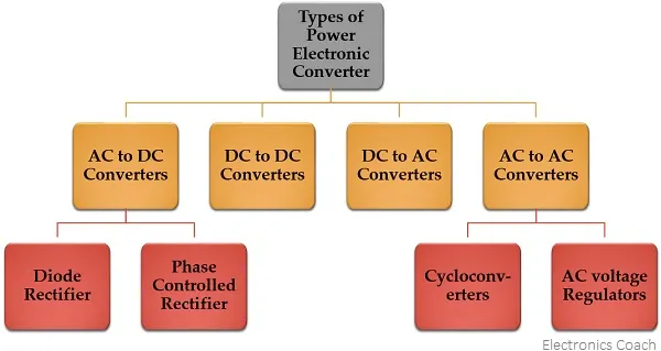
- Let us now understand each type separately.
- AC to DC Converters
- A type of converter that changes input AC signal into a DC is known as AC to DC converter. We have already learned in basic electronics that the devices that convert the AC signal into DC signal are known as rectifiers.
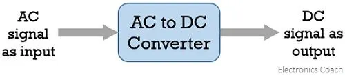
- Diode Rectifiers: This rectifier circuit changes applied ac input voltage into a fixed dc voltage. Either a single-phase or three-phase ac signal is applied at the input. These are mainly used in electric traction and in electrochemical processes like electroplating along with in battery charging and power supply. These are also used in welding and ups related services.
- Phase Controlled Rectifiers: Unlike diode rectifiers, phase-controlled rectifiers are designed to convert a fixed value of ac signal voltage into a variable dc voltage. Here line voltage operates the rectifier hence these are sometimes known as line commutated ac to dc converters. Similar to diode rectifiers, here also the applied ac signal can be a single-phase or three-phase ac signal. Its major applications are in dc drives, HVDC systems, compensators, metallurgical and chemical industries as well as in excitation systems for synchronous machines.
- DC to DC Converters
- The converters that convert the dc signal of fixed frequency present at the input into a variable dc signal at the output are also known as choppers. Here the achieved output dc voltage may have a different amplitude than the source voltage. Generally, power transistors, MOSFETs, and thyristors are the semiconductor devices used for their fabrication. The output is controlled by a low power signal that controls these semiconductor devices from a control unit.
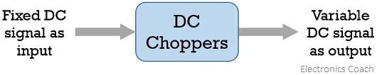
- Here forced commutation is required to turn off the semiconductor device. Generally, in low power circuits power transistors are used while in high power circuits thyristors are used.
- Choppers are classified on the basis of the type of commutation applied to them and on the basis of the direction of power flow. Some major uses of choppers are in dc drives, SMPS, subway cars, electric traction, trolley trucks, vehicles powered by battery, etc.
- DC to AC Converters
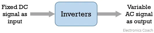
- The devices that are designed to convert the dc signal into ac signal are known as inverters. The applied input is a fixed dc voltage that can be obtained from batteries but the output obtained is variable ac voltage. The voltage and frequency of the signal obtained are of variable nature. Here the semiconductor device i.e., the thyristor is turned off by using either line, load, or forced commutation.
- Thus, it can be said that by the use of inverters, a fixed dc voltage is changed into an ac voltage of variable frequency. Generally, the semiconductor devices used for its fabrication are power transistors, MOSFETs, IGBT, GTO, thyristors, etc.
- Inverters mainly find applications in induction motor and synchronous motor drives along with UPS, aircraft, and space power supplies. In high voltage dc transmission system, induction heating supplies as well as low power systems of mobile nature like flashlight discharge system in photography camera to very high power industrial system.
- Like choppers, in inverters also conventional thyristors are used in high power applications and power transistors are used in low power applications.
- AC to AC Converters
- An ac to ac converter is designed to change the ac signal of fixed frequency into a variable ac output voltage.
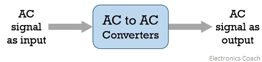
- There are two classifications of ac to ac converters which are as follows:
- Cycloconverters: A cycloconverter is a device used for changing ac supply of fixed voltage and single frequency into an ac output voltage of variable voltage as well as different frequency. However, here the obtained variable ac signal frequency is lower than the frequency of the applied ac input signal. It adopts single-stage conversion. Generally, line commutation is mostly used in cycloconverters however forced or load commutated cycloconverters are also used in various applications.
- These mainly find applications in slow-speed large AC traction drives such as a rotary kiln, multi MW ac motor drives, etc.
- AC Voltage Controllers (AC voltage regulators): The converters designed to change the applied ac signal of fixed voltage into a variable ac voltage signal of the same frequency as that of input. For the operation of these controllers, two thyristors in an antiparallel arrangement are used. Line commutation is used for turning off both the devices. It offers the controlling of the output voltage by changing the firing angle delay.
- The major applications of ac voltage controllers are in lighting control, electronic tap changers, speed control of large fans and pumps as well
2.ans:
given parameters are
battery pack voltage=72v
rated aemature current=400A
armature resistance Ra=0.5
motor constant k=0.7
chopper switching frequency=400hz
duty cycle=70%
sol:
vehicle output voltage=battery volts*duty cycle
=72*0.70=50.4v
i.e the vehicle voltage is 50.4v
now the equ of vehicle
Tu=Vu. (Kϕ/Ra)-((Kϕ)^2/Ra)*ω -------1
where
Tu=vehicle torque
Vu=vehicle voltage
ω=steady state constant
kϕ= motor constant
Ra=armature resistance
substituting all values
Tu=((50.4*0.7)/0.5)-(((0.7)^2)/0.5)*ω ......2
=70.56-0.98ω
now the vehicle speed torque char is given as
 ....3
....3
at steady state condition
eq 3=eq 2
24.7+0.0051ω^2=70.56-0.98ω
then 0.0051ω^2-0.98ω-45.86=0
solve the above equ by using quadratic eq
ω=(-b+/-√(b^2-4ac))/2a
ω=(-0.98+/-√(0.98^2-(4*(0.0051)*(-45.86)))/2*0.0051
=(-0.98+/-1.377)/0.0102
=38.92rad/sec -231.07rad/sec
so the steady state speed of the vehicle is 38.92 rad sec
3.ans:
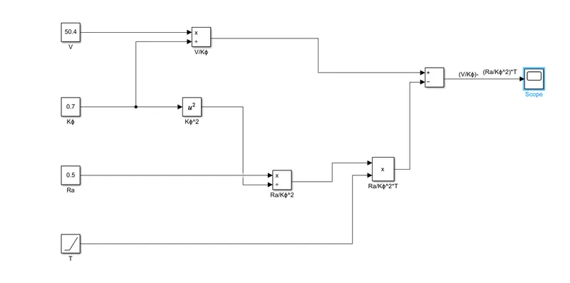
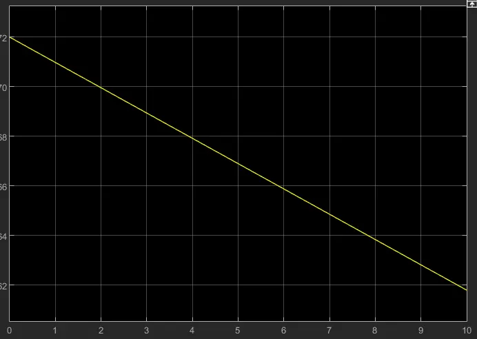
let us consider above question values
v=50.4
kϕ=0.7
Ra=0.5
4.ans:
wally rippel is a long-time proponent of electric vehicels. Prior to joining Tesla Motors, he was an engineer at aerovironment., where he helped develop the ev1for General Motors and was featured in the documentary movie, eho killed the electric car? Wally has also worked for jet propulsion laboratary on electric vehicle battery research, among other projects. In 1968, as a Caltech undergraduate student, he built an electric car (a converted 1958 Volkswagen microbus) and won the great transactions electric car race against MIT.
according to the blog induction vs dc brushless motors by wally ripple,tesla,the writter state the changes in the world years ag0and the latest technology trends that are happening .he expalins dc brudhless motor and imnduction motor
DC brushless machines:
With brushless machines, the rotor includes two or more permanent magnets that generate a DC magnetic field (as seen from the vantage point of the rotor). In turn, this magnetic field enters the stator core (a core made up of thin, stacked laminations) and interacts with currents flowing within the windings to produce a torque interaction between the rotor and stator. As the rotor rotates, it is necessary that the magnitude and polarity of the stator currents be continuously varied – and in just the right way - such that the torque remains constant and the conversion of electrical to mechanical energy is optimally efficient. The device that provides this current control is called an inverter. Without it, brushless motors are useless motors.
the author also said that a brushless dc motor produces no starting torque when directly connected to fixed frequency utility power .they really need the aid of an inverter whose phase is maintained in step with the angukar position of the rotor
advantages:
1.there is a low haeat generation in the rotor and its cooling capacity is better as compared to the induction motor
2.it has high peak point efficiency and can also operete in unity power factor. where as 85%is is the best p.f
disadvantages:
1.machine size increases magnetic losses increases due to this efficeincy decreases.
2.permenent magnets are expensive and difficult to handle due to very forces.
induction motor:
Let’s move on to induction motor drives. A forerunner of the 3-phase induction motor was invented by nikolos tesla sometime before 1889. Curiously, the stators for the 3-phase induction motor and the DC brushless motor are virtually identical. Both have three sets of “distributed windings” that are inserted within the stator core. The essential difference between the two machines is with the rotor.
the authour says that.Unlike the DC brushless rotor, the induction rotor has no magnets – just stacked steel laminations with buried peripheral conductors that form a “shorted structure.” Currents flowing in the stator windings produce a rotating magnetic field that enters the rotor. In turn, the frequency of this magnetic field as “seen” by the rotor is equal to the difference between the applied electrical frequency and the rotational “frequency” of the rotor itself. Accordingly, an induced voltage exists across the shorted structure that is proportionate to this speed difference between the rotor and electrical frequency. In response to this voltage, currents are produced within the rotor conductors that are approximately proportionate to the voltage, hence the speed difference. Finally, these currents interact with the original magnetic field to produce forces – a component of which is the desired rotor torque.
When a 3-phase induction motor is connected to utility type 3-phase power, torque is produced at the outset; the motor has the ability to start under load. No inverter is needed. (Were an inverter needed, Tesla’s invention would have been useless until sometime in the 1960s.) The fact that induction motors are directly compatible with conventional utility power is the main reason for their success. In contrast, a brushless DC motor produces no starting torque when directly connected to fixed frequency utility power. They really need the aid of an inverter whose “phase” is maintained in step with the angular position of the rotor.
advantages:
1.it doesnot have any magnets and in this magnetisc feild is adujastable.motor has the ability to start under load there is no need of an inverter.
2.magnetic feild is proporstional to v/f ratio.this technology is used to reduce the magnetic losse and conduction losses.efficiency remains at max.
disadvantages:
1.it requires only ac.shaft speed is proportionate to line frequency.hence when used the utility power factor they are constant spees machine.
conclusion
my conclusion is that DC brushless drives will likely continue to dominate in the hybrid and coming plug-in hybrid markets, and that induction drives will likely maintain dominance for the high-performance pure electrics. The fact that so much of the hardware is common for both drives could mean that we will see induction and DC brushless live and work side by side during the coming golden era of hybrid and electric vehicles.