Week-7 Challenge: DC Motor Control
1a answer:
DC_hbridge matlab model
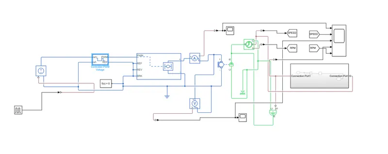
1.in this 0-5 V pulse with 50 percent duty and time period 30 seconds is given as input to controlled PWM voltage.
2.in controlled pwm source switching frequency is set to 4000Hz. when input voltage to it is 0v then duty cycle set to 0% and when input voltage is 5 volts duty cycle was 100%. the output of this block is 12 V between PWM and ref ports.
3.the Hbridge output is connected to motor block which as access to connect to load and also to measure speed and angular velocity using ideal motion rotational sensor using C and R ports.
4. load torque is taken as fan load and calculated from speed measured from motionsensor and given as input to motor block.
5.tried to run the simulation but error has occurred .
1c answer :
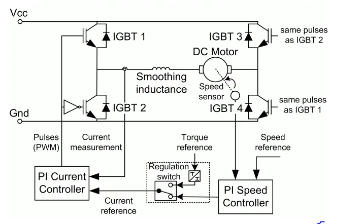
1.In this 200 HP DC motor is separetly exicted with a constant 150V DC field voltage source.
2.The IGBT converter is fed with 515V DC bus obtained by rectification of 380V,50Hz voltage source.
3.The armature voltage is provided by an IGBT converter controlled by two PI controllers.first regulator is speed regulator and second regulator is current regulator.
4.speed regulator outputs current reference as input to the current regulator.current regulator controls the armature current by comparing the appropriate duty cycles of 5KHz pulses of IGBTS .IGBT1 and IGBT4 are opposite to IGBT3 and IGBT2.
Result after running the DC7 matlab file.
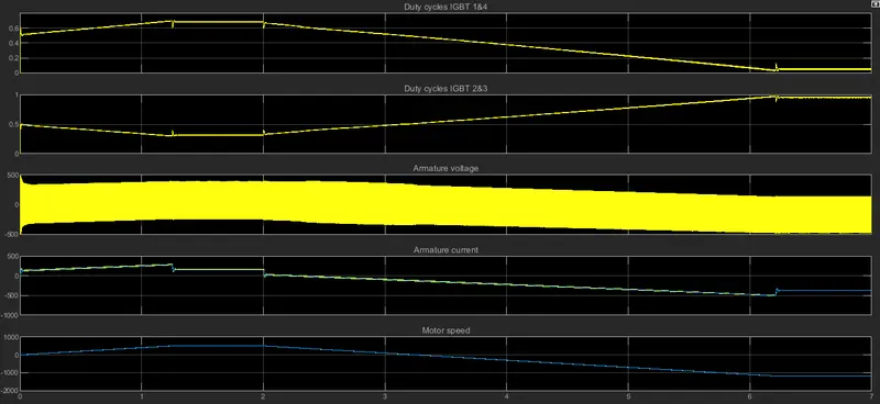
5. until 2 seconds speed reference is positive so igbt1 and igbt 4 will operate or more time. after 2 seconds speed reference was negative so duty cycle of igbt2 and igbt3 will increase and motor will try to operates in reverse motoring mode.After 6 seconds duty cycle of igbt1 and igbt4 becomes zero and armature current also becomes constant negative current when motor attaines reference negative speed.
6.The dierence between normal H bridge model and dc7 4 quadrant chopper drive is closed loop control was done in dc7 model where as in H bridge model is open loop control.
2 answer :
two quadrant type c chopper matlab simulink image
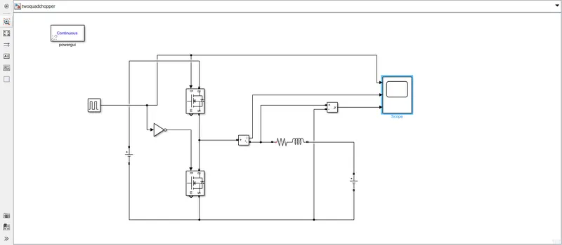
1.Type C 2 quadrant chopper was built in simulink using two mosfets.since mosfets are having internal diodes there is need to connect parallel diodes across mosfet switches to make type c chopper.
2.since dc motor armature equivalent circuit nothing but armature resistance and inductance in series with opposing back emf, so it is modelled as all three resistance ,inductance and opposing voltage source in series .
3. in simulation armature resistance taken as 0.2 ohms,inductanace as 5mH and back emf as 20V.
4.Input voltage to chopper is taken as 48V.
5.lower mosfet will be off when upper mosfet is on.
simulation result after running two quadrant chopper file.
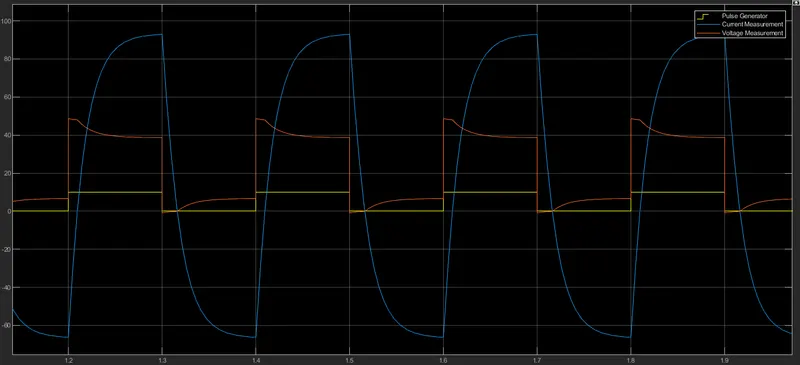
6.from simulation it can be seen that armature voltage of motor is always positive since it is two quadrant chopper, where as armature current is negative when bottom mosfet switch operates and motor works in forward braking mode.
3 answer :