Week-7 Challenge: DC Motor Control
1. AIM
A. To explain a MATLAB demo model named ‘Speed control of a DC motor using BJT H-bridge’.
B. To Comment on the armature current shoot-up from the scope results.
C. To compare the H-bridge model with the four-quadrant chopper DC drive(DC7) block
A. speed control of DC motor using BJT H-bridge
EXPLANATION
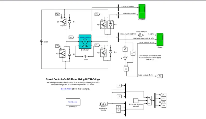
- Open the demo model speed control of DC motor using BJT H-bridge.
- The BJT operates as an IGBT when used for power switching applications, therefore, the IGBT block is used to model the BJT device.
- The DC motor uses a preset model (5 HP 24V 1750 rpm) and field voltage 300V.
- here fan type load is considered. ie, torque load is proportional to the speed^2.
- here the Torque TL is the mechanical input of the DC machine
- the switches of the above H-bridge are controlled by switch block (1 or 0), which is given to P1, P2, P3, P4.
- the armature mean voltage can be varied by varying the duty cycle in the pulse generator.
- scope and current scope are used to observe the plots and results
WORKING
- There are 4 switches Q1, Q2, Q3, Q4, and 4 free-wheeling diodes D1, D2, D3, D4.
- when Q1 and Q4 are switched on, the positive voltage is supplied and the dc motor runs in the forward direction. (current flows through Q1 -- motor -- Q4)
- when they are switched off, D2 and D3 act as free-wheeling diodes.
- when Q3 and Q2 are switched on, the voltage from the positive terminal of the circuit is connected to the negative terminal of the DC motor, hence negative voltage is supplied and the DC motor runs in the reverse direction. (current flows through Q3 --- motor --- Q2).
- when they are switched off, D4 and D1 act as free-wheeling diodes.
The D3 and Q3 currents are observed through currents scope, while the speed, armature current from DC motor, and load torque are observed through another scope.
CURRENT SCOPE:
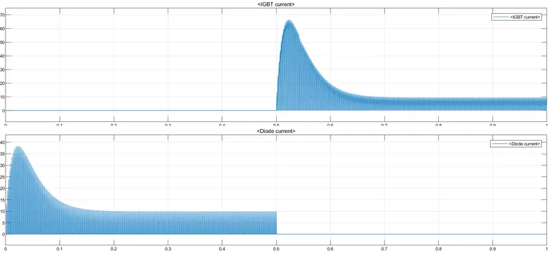
- here we can observe that from 0 to 0.5 sec, diode currents are present and from 0.5 to 1 sec, IGBT currents are present.
- that explains the freewheeling diode D3 state when Q1, Q4 is switched off and IGBT current when Q3 is switched ON.
B. To Comment on the armature current shoot-up from the scope results.
- The below are the result scopes when the duty cycle (pulse width) is 75%
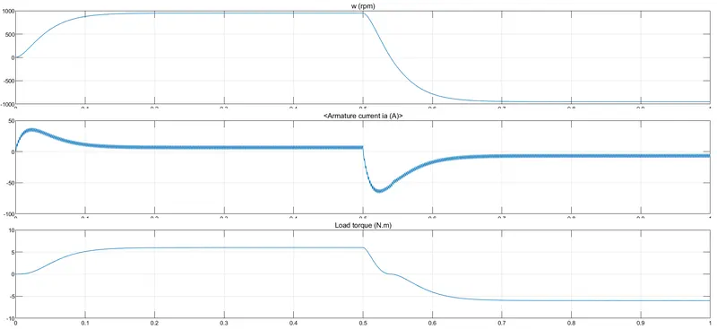
- here from 0 to 0.5 sec, DC motor runs in the forward direction (forward motoring) and after 0.5 sec in the reverse direction (reverse motoring).
- the initial shoot up in armature current indicates the starting current of the motor.
- after 0.5, the motor changes its direction resulting in a more negative current initially and becoming constant negative current later.
- this shoot-up can be reduced by reducing the duty cycle % (pulse width).
V_o = V_bat * duty cycle %
= 240 * 75 / 100
= 180 v
- so by controlling the duty cycle %, we are controlling the voltage, which controls the current.
- lets reduce the duty cycle to 50 %
V_o = V_bat * duty cycle %
= 240 * 50 / 100
= 120 v
- hence reducing the voltage will result in reducing the current shoot-up
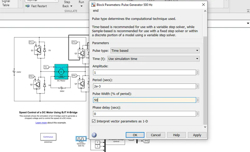
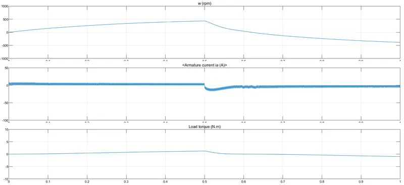
- here we can observe that the shoot-up of negative armature current is reduced when compared to duty cycle (pulse width) of 75%
C. To compare the H-bridge model with the four-quadrant chopper DC drive(DC7) block
H-bridge model
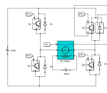
- Either Q1, Q4 is switched on simultaneously or Q3, Q2 is switched on.
- positive voltage results in forwarding motoring
- negative voltage results in reverse motoring
- only two modes can be achieved
- the IGBT switches P1, P2, P3, P4 are controlled by armature voltage control and duty cycle (pulse width)
Four-quadrant chopper DC drive (DC7)
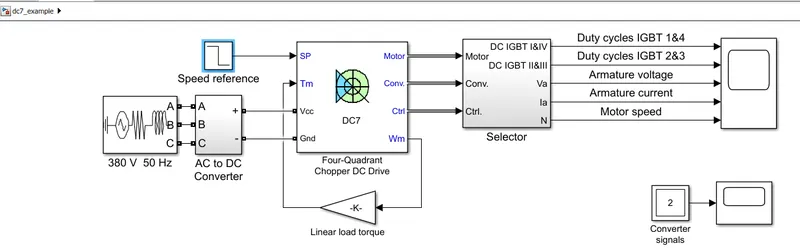
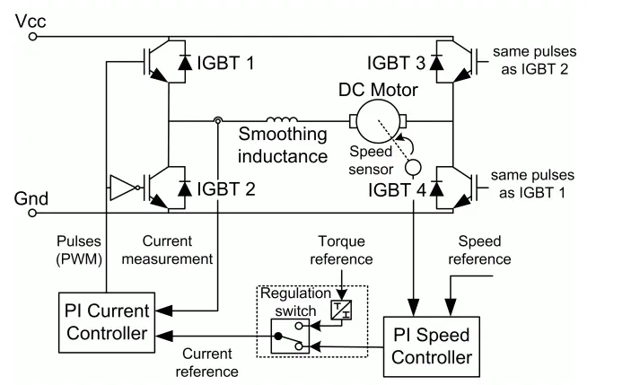
- IGBT 1, 2, 3, 4 can be controlled separately by using 2 PI regulators
- speed controller inputs the speed reference, ie accelerating or decelerating, and outputs the current reference
- then accordingly the current controller controls the armature current by computing the appropriate duty ratios of the 5 kHz pulses of the four IGBT devices. (inputting signal to the IGBT's).
- smoothing inductance is used in order to limit the amplitude of the current oscillations.
- a braking chopper has been added between the diode rectifier and the DC7 block since dynamic braking mode is possible.
- four modes are possible forward motoring, reverse motoring, forward braking, and reverse braking.
2. AIM
- To develop a 2-quadrant chopper using Simulink & explain the working principle with the relevant results.
TWO - QUADRANT CHOPPER
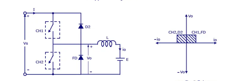 source: google
- this type of chopper operates in the first and second quadrants.
- the arrangement is made like the above figure, two switches (CH1, CH2), two diodes (FD, D2), DC voltage source (Vs), inductor (L), and load.
- we cannot switch on both CH1 and CH2 simultaneously (at the same time).
FIRST - QUADRANT
- During the first quadrant, CH1 is switched on, the current flows from the source to the load through CH1 and L. when CH1 is switched off, the current will flow through the FD (freewheeling diode), L, and load. both the voltage and current remain positive.
SECOND - QUADRANT
- During the second quadrant, CH2 is switched on, the voltage from the source (Vs) is stopped. here the current produced from the load will flow through L, CH2. when CH2 is switched off, the current will flow through L, D2 (diode2), and to the source. the voltage will be positive, but the current will be negative since the direction flow is changed and it will be flown back to the source.
SIMULINK MODEL
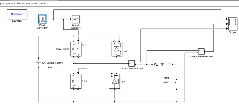
- the pulse generator is used to generate pulse (on/off).
- NOT logical operator is used since both CH1 and CH2 should not be switched on simultaneously.
- DC voltage source is 240V and load side voltage is 100V. RLC load is used.
- current measurement block and voltage measurement block are connected to load and used to measure them.
- the scope block will be showing the output from the pulse generator, current, and voltage measurement blocks.
- finally, powergui block is added for the simulation.
- the sample time taken here is 10.
OUTPUT
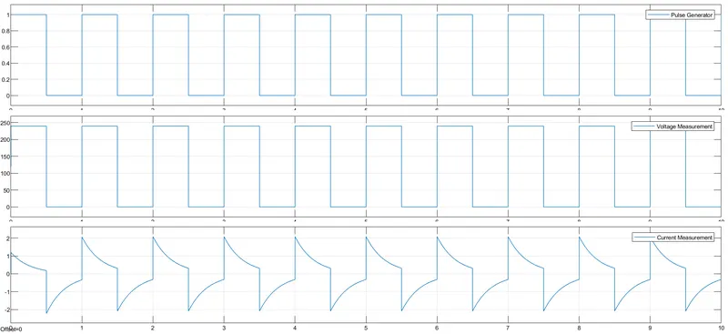
- Here we can observe that the voltage remains positive and the current becomes positive and negative indicating the 2-quadrant chopper operations.
RESULT
- Thus a 2-quadrant chopper using Simulink is developed and explained with the relevant results.
3. Explain in a brief the operation of the BLDC motor
Brushless DC motor
- They have a stator (stationary) and a rotor (moving). the rotor consists of permanent magnet, while the stator has 3 phase winding.
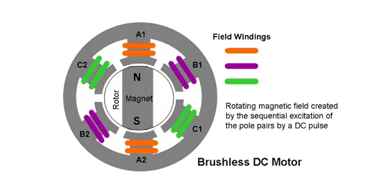
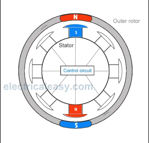 source: google/electricaleasy.com
OPERATION
- Generally, the magnets will have north and south pole. by the nature of magnets, the same pole repels each other and the opposite pole attracts each other. the same concept is used for rotating the rotor of the BLDC motor.
- The rotation of the rotor depends on how the 3 phase stator windings are energized.
- the stator 3 phase windings (A, B, C) will become electromagnets when they are given DC.
- the rotor has a permanent magnet and stator windings act like magnets when current is given.
for easy understanding,
DC has applied to stator A-winding, now the A-phase winding will have north and south poles. when the north pole of the rotor comes in contact with the south pole of the stator A-winding they will attract each other. but before this happens, the stator A-winding is de-energized and the stator B-winding is energized. now the north pole of the rotor is automatically attracted to the south pole of stator B-winding. then stator B-winding is de-energized and C-winding is energized, now again the north pole of the rotor moves towards the south pole of the stator C-winding.
once the north pole of the rotor completes the cycle in catching up with the south poles of all A, B, C windings, the south pole of the rotor will come in contact. now we will change the polarity of the windings supply, creating north poles in stator windings (A, B, C). thus keeping the rotor rotating.
the poles (north, south) of the rotor will never get the poles (south, north) of stator windings (A, B, C). the rotor keeps on getting attracted to the stator windings resulting in rotation.
- Hall sensors are used to find the rotor position, accordingly the current to windings and their polarity can be controlled.
- the speed of the rotor can be controlled by controlling the voltage.
Advantage
- maintenance-free
- less noise
- high efficiency
- reliability and long term
Disadvantage
- complex construction
- expensive than brushed DC.
- electronic controllers are required
REFERENCE
https://skill-lync.com/student-projects/multi-quadrant-operation-of-dc-motor-in-simulink
Matlab help documentation - two-quadrant dc chopper, speed control of dc motor using BJT-H bridge, four-quadrant dc chopper drive DC7.
Google drive link:
https://drive.google.com/file/d/1zlghTT3cjLAl6jCcPBfTRG11DuBQP1tC/view?usp=sharing