Week -2
1. AIM:
- To make a Simulink model of Doorbell using a solenoid block
- To create a situation where the switch is closed for 2 seconds, then released and observe the physical movement of the plunger in the solenoid block.
SIMULINK MODEL:
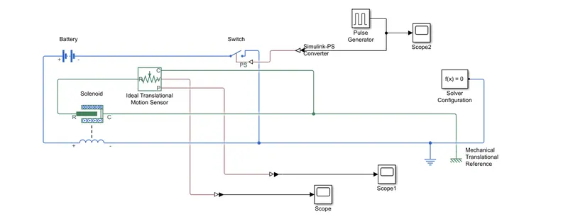
EXPLANATION:
PULSE GENERATOR
- It is used to generate pulse, which will be given to the input physical signal of the switch
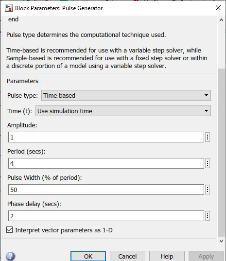
- The parameters of pulse generator block is given according to the favorable input. these include amplitude, period, pulse width and phase delay
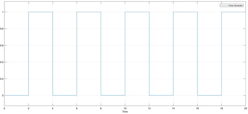
- This Simulink signal is then converted to physical signal by simulink-ps converter and given to input physical signal of the switch
SWITCH
- The switch is controlled by the physical signal from the pulse generator. if the signal is greater than the threshold then the switch is closed otherwise it is opened.
BATTERY
- The battery acts as the power source for the circuit
SOLENOID
-
This block implements the electrical and mechanical characteristics of a solenoid. the + terminal of the battery is connected to the + terminal of the solenoid block and the - terminal is connected to the electrical reference.
-
the mechanical characteristics are R and C. When energized, magnetic field builds up which pulls a plunger or armature (R in our case). the case (C) is connected to the mechanical translational reference.
IDEAL TRANSLATIONAL MOTION SENSOR
- This block is used for observing the motion of the plunger (R).
- The R(positive probe) of this block is connected to the R of solenoid block and C(reference probe) is connected to the mechanical reference
- Connection V and P are the physical signal output ports for velocity and position.
SCOPE AND SOLVER CONFIGURATION
- The scope is used for observing the input/output signal graphically.
- The Solver Configuration block is required for every model before you begin simulation.
WORKING
The pulse generator creates signal, which is given to the switch block. when the switch is closed, the electrical circuit gets closed. then inside the solenoid block, when energized, a magnetic field builds up, and the plunger moves. this plunger is connected to the ideal translational sensor block. from the V and P output ports of the sensor block, we can observe the velocity and position through the scope.
OUTPUTS
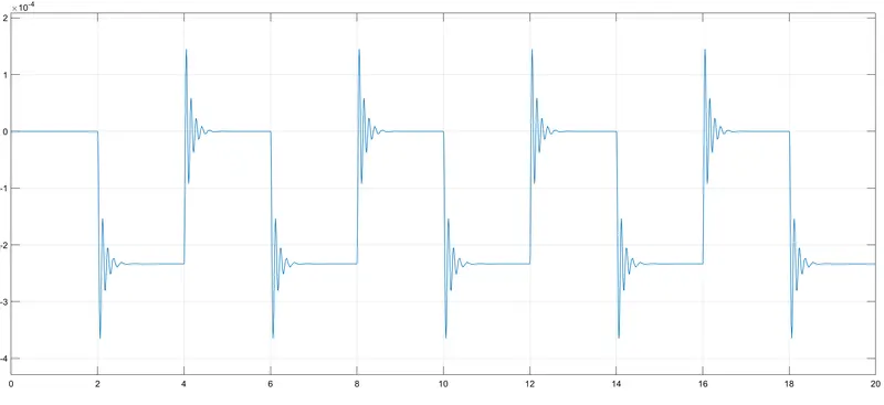
- Here we can see the variation in position of plunger ie. when the switch is closed for 2 seconds the ideal translational sensor shows these variations.
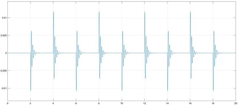
- Here we can see the variation in the velocity.
RESULTS
- Thus a simulink model of a doorbell using solenoid block is created and the physical moment of plunger is observed.
2. AIM
- Use a thermistor to sense the temperature of a heater & turn on or turn off the fan
OBJECTIVE
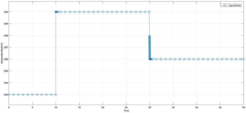
- Given temperature source 20 °C (293 K) from 0 to 10 seconds, 27 °C (300 K)from 10 to 30 seconds, 23 °C (296 K)from 30 to 50 seconds
- The fan should be ON when the temperature is above 25 °C (298 K)and OFF when it is below.
SIMULINK MODEL
EXPLANATION
SIGNAL BUILDER
- It is used to create signal, which will be given as the input signal for temperature source.
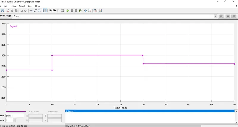
- Here we have created signal with time 0-50 sec and temperature range between 293 - 300 kelvin.
CONTROLLED TEMPERATURE SOURCE
-
This block represents an ideal energy source in a thermal network that can maintain a controlled temperature difference regardless of the heat flow rate.
- The temperature difference is set by the input from the physical signal port S.
THERMISTOR
- The Thermistor block represents a Negative temperature coefficient thermistor. NTC thermistors are resistors with a negative temperature coefficient, which means that the resistance decreases with increasing temperature.
VOLTAGE SENSOR
- Represents an ideal voltage sensor, that is, a device that converts voltage measured between any electrical connections into a physical signal proportional to the voltage.
SWITCH BLOCK
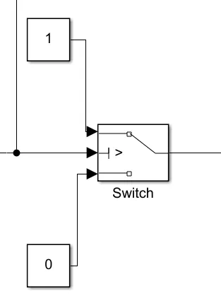
- Here the switch block has three input ports, port1 is connected with constant 1 (true condition), port 3 is connected with constant 0 (false condition), and port 2 is connected with the input signal from the voltage sensor. we can set the condition for port 2 ie. threshold.
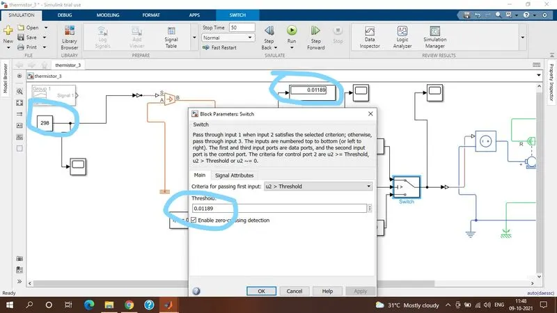
- The threshold is set to 0.01189, which we receive from the voltage sensor for the temperature 298 k. so when the input from voltage sensor is above the threshold (0.01189) the switch satisfies port 1 and is ON, otherwise satisfies port 3 and is in OFF condition.
CONTROLLED VOLTAGE SOURCE
-
Represents an ideal voltage source that is powerful enough to maintain the specified voltage at its output regardless of the current passing through it.
DC MOTOR
-
Represents the electrical and torque characteristics of a DC motor. The + and - terminal are connected to the electrical circuit. the port C and R are connected to the mechanical rotational reference and port.
IDEAL ROTATIONAL MOTION SENSOR
-
This block measures angular velocity or angle in a mechanical rotational network.
-
The physical signal ports W and A report the angular velocity and angle, respectively, of port R relative to port C.
SCOPE - This block is used to visualize the results graphically
DISPLAY - this is used to display the results.
SOLVER CONFIGURATION - every physical model should be connected with a solver configuration before we begin the simulation.
WORKING
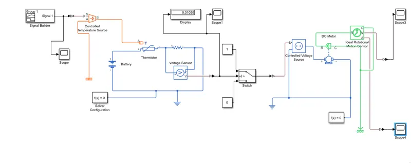
The signal builder creates the input signal with respect to the specified time and temperature. then the signal is converted as a physical signal through Simulink to ps converter and given to the controlled temperature source S. then the output from port B is given to the input thermal port of thermistor. the thermistor alters its resistance characteristics with temperature. a resistor is connected to the thermistor with a voltage sensor to measure the voltage across the resistor. a battery is connected to the circuit for the power supply. the output signal from the voltage sensor is converted to Simulink signal through ps-Simulink converter and connected to the input port of the switch block. the signal from the voltage sensor is also connected to scope and display for observing the results. so when the switch is ON the DC motor receives the signal from a controlled voltage source and the IRMS sense the angular velocity and angle with respect to the signal received from the DC motor. the physical signal ports W and A of IRMS are then connected to ps-Simulink converter and then to scope for observing the output results graphically.
OUTPUTS
1. signal builder (time vs temperature)
2. physical signal from voltage sensor vs time
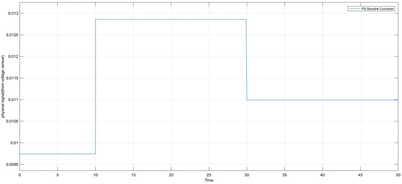
- According to the signal builder signal, the physical signals are created from the voltage sensor.
3. Angular velocity vs time
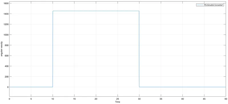
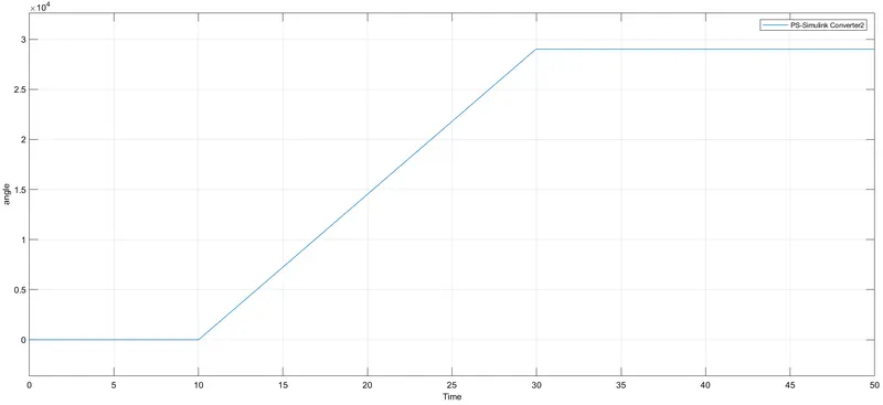
- Here we can observe the angular velocity variation between 10 - 30 seconds, where the temperature specified is 27 °C (300 k).
- Switch gets ON and the DC motor runs only when the temperature is above 25 °C and OFF when below 25°C.
4. Angle vs time
RESULTS
- Thus a thermistor block is used to sense the temperature of a heater (controlled temperature source) & turn on or turn off the fan (DC Motor)
REFERENCE - Simulink library browser, help documentation. FAQ.