Week-7 Challenge: DC Motor Control
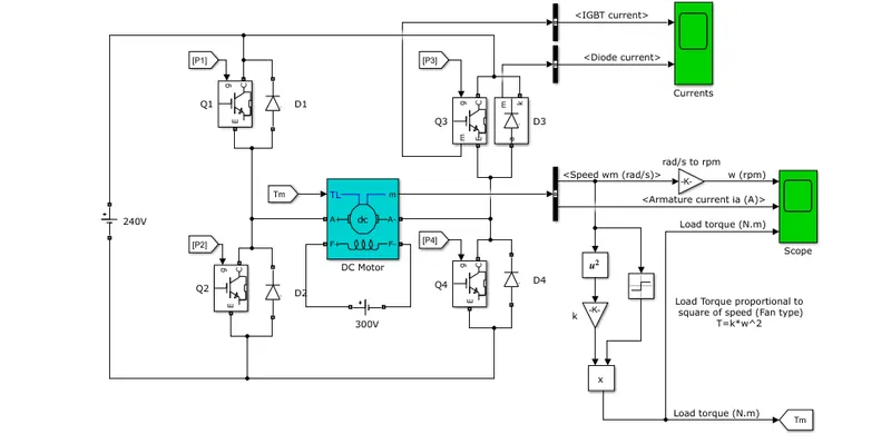
Question 1. A. Explain a MATLAB demo model named ‘Speed control of a DC motor using BJT H-bridge’.
B. Comment on the armature current shoot-up from the scope results.
C. Refer to the help section of ‘The Four-Quadrant Chopper DC Drive (DC7) block’. Compare it with the H-bridge model.
A. Explain a MATLAB demo model named ‘Speed control of a DC motor using BJT H-bridge’.
MODEL:-
PULSE GENREATOR:-
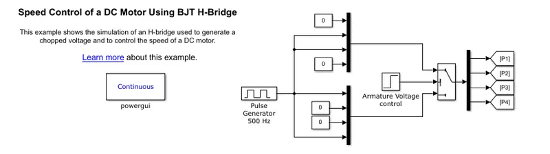
Here in the model four switches are used thus four signal are genereted accordingly.
Working Of H-Bridge Model:-
- Here H-Bridge DC chopper circuit is designed to control the speed of the motor.
- IGBT & BJT are power switching Devices.
- Four IGBT switches are used for inveting the DC Voltage 0 to 240v supply. The current flows from collector (C) to emittor (E).
- The gate are controlled by the pulse (0 to 1) according to armature voltage of mototr given by pulse genrerator.
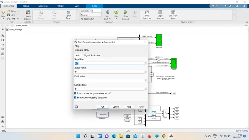
- This image shows that voltage value given from intial to final during the step time. according to the pulse on and off the voltage supplied to the IGBT's.
- Here the four switches are used Q1,Q2,Q3,Q4. pulses P1,P2,P3,P4 are connected with corresponding switches.
- in 1st state , Q1 and Q4 Are closed by giving 1V. to IGBT's , current from battery passes through Q1and Q4. diode D2,D3 are used as free whiling diode in this state. in this case forward motoring and foraward braking are held.
- in second state , Q2 and Q3 are closed by giving one hold to IGBT's , current from battery passes through Q2 and Q3 .diode D1,D4 are used as free whiling diode in this state. in this case reversed motoring and reversed braking are held. th current dirction change its dirction in this state.
- Both the state occuring 0.5 sec in their sample time. thus DC supply converted and feeded to the armature of the motor.
- Here free whiling diode are used as a saftey purpose of these inverter circuit as when flow of current on low values protects the circuit and machine by field backing thr current in high voltage fluctuation voltage get splited as protection to the motor and circuit compoents.
- in motor operation aremature terminal are connected with a 240V along the inverter circuit and field winding are connceted with 300V DC supply to act as a electromagnet for the Motor.
- Here run this Demo model and study the from scope.
Result:-
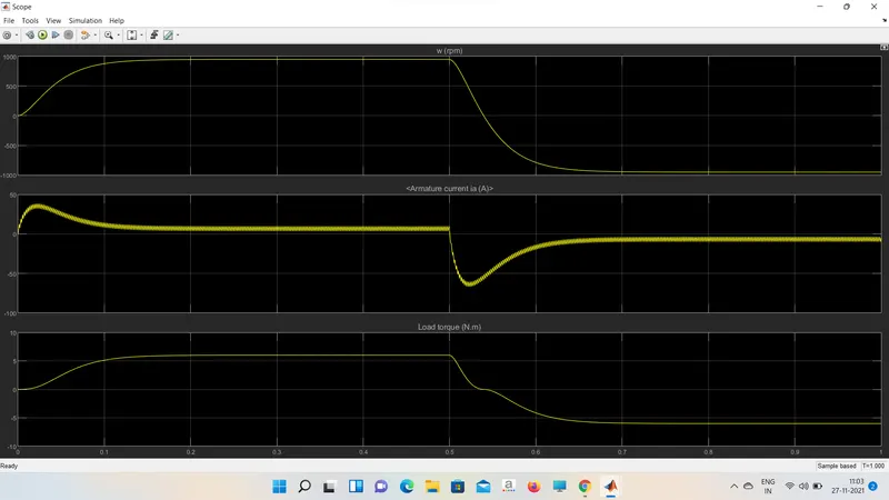
SPEED OF MOTOR:-
- Intially speed increases to 0 to nearly 900 rpm upto 0.5 sec ( forward motoring action take place.)
- Then speed reduces to 0 rpm (forward Dynamic braking action take place.)
- Intially speed increases to 0 to nearly 900 rpm upto 1 sec ( Reverse motoring action take place.)
- reverse Dynamic braking action take place ( not shown in scope).
B. Comment on the armature current shoot-up from the scope results.
we can change the duty cycle to 45% (120v) and seen the results
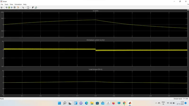
Conclusion :- Thus to reduce the shoot-up armature current we have to change duty cycle gradually from 0 to 100% that inturns increases voltage gradually and speed also change accordingly.
C. Refer to the help section of ‘The Four-Quadrant Chopper DC Drive (DC7) block’. Compare it with the H-bridge model.
MODEL:-
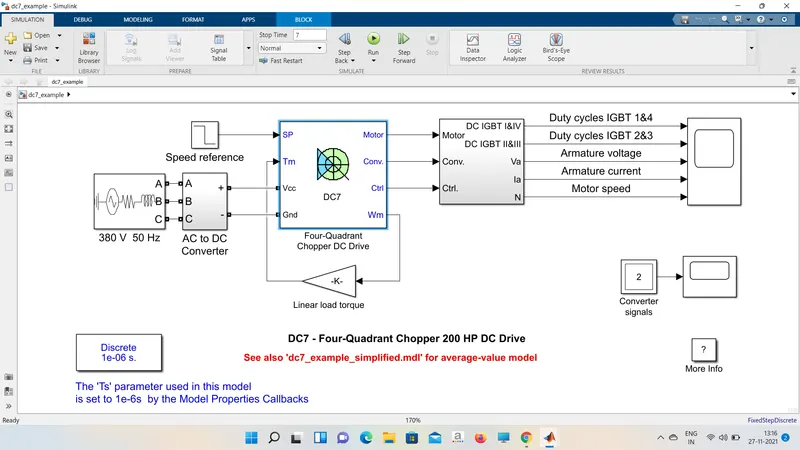
Connections :-
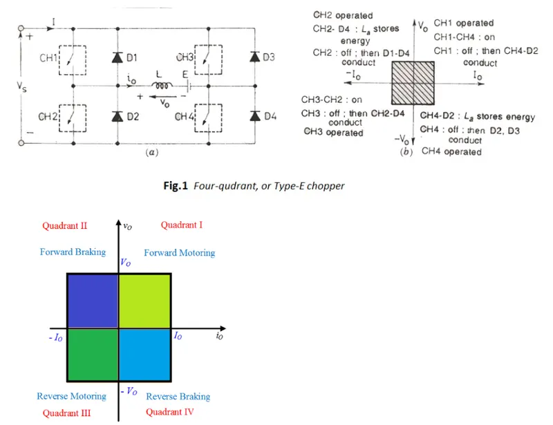
Working :-
- Here Four IGBT Switches are used.
- Here pulses are given from PI current controller , that controls the pulses by compairing armature current measurement and current refrence.
- Current refrence can be generated by using regulation switch in that torque refrence and PI speed controller pulses. that internally compared by speed of motor and refrence speed as input.
- Mainly speed controlled by current controller.
- in this case four quadrant operations are performed.
- Forward motoring mode , forward regenrative braking mode : CH1 , CH4 are ON and CH2 ,CH3 are in OFF.
- Reverse motoring mode , Reverse regenrative braking mode : CH2 , CH3 are ON and CH1 , CH4 are in OFF.
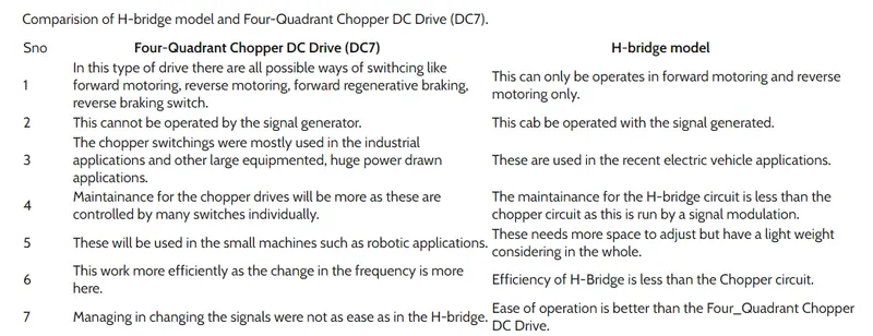
Question 2:- Develop a 2-quadrant chopper using simulink & explain the working of the same with the relevant results.
Model:-
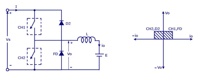
Where,
Vs = DC Voltage Source
CH1 = Power electronics switch 1
CH2 = Power electronics switch 2
D2, FD = Free whiling Diodes
L = Inductor Load
E = Back EMF from load
Operations :-
- Here either one should be on at a time , either CH1 or CH2
- if CH1 is on the current flows from source poisitive to load (Here DC Motor ) passes through L and E to negative terminal of source ( 1st quadrant).
- if CH1 is off the FD diode conducts and complete the circuit , ( L - E - FD - L) as stored energy in inductor L the voltage across is also positive voltage , current dirction also positive
- Now if CH2 is on , current flow from E (Load current) complete the circuit ( L- CH2 - E )
- if CH2 gets off , the current passes through D2 towards source complete the circuit (E - L - D2 - Positive source - negative source - E).
- in this stage regenerative braking occurs ( 2nd quadrant)
- This cycle contionous again up to stop time .
Model:-
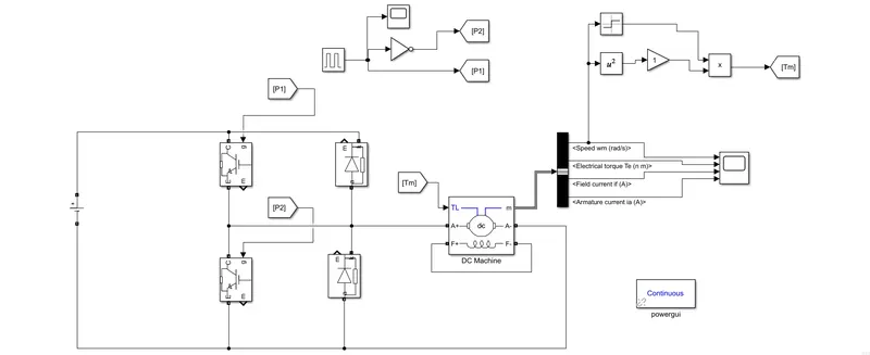
Working:-
Pulses for the two IGBT Switches are given by using pulse generator and NOT logical operation for alternative switch ON/OFF.
Here dc machine is used and load torque is given as input to the motor
The motor parameters are given to scope for result.
Duty cycle is given as 65% for simplicity period is at 1 sec.
Result:-
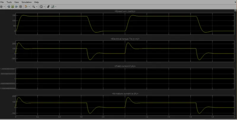
the scope shows that,
Speed increases in 1st quadrant as forward motoring action. current is in poisitive direction
speed reduces at OFF time , so current get set back to source as regenrative braking mode when CH2 is open up.
Torque changes according to the speed crossing zero and produce regenrative torque while in second quadrant.
Question 3. Explain in a brief about operation of BLDC motor.
It is a Brushless DC motor with electronics commutator
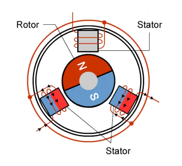
Here we have an elctronics eommutator or a power converter where it energizes different turn by turn.
Most of the brushless DC motor are of three phase type
For brushed type DC motor , there is no harm in working it with no load but here we cannot connect simply a voltage terminal across the brushless type because type because it have threee terminals . so to connect a three terminal mototr with two terminal source we need a commutator in between.
The rotor have fixed permant magnet that is why it is called a permant magnet brushless DC Motor.
The stator have core with windings . when current flows through tje pole it acts as a magnet.
Three phase current have to be maintained synchronously in a such way that the motor rotates in clockwise / anti - clockwise direction.
There are two arrangement in which BLDC motor works.
1. Trapezoidal arrangement
2. sinasoidal arrangement
The input waveform provided to the stator side of the BLDC motor for the respective arrangement is shown below.
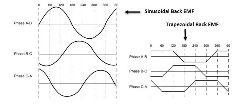
The BLDC Motor is also use as Hall effect Sensor
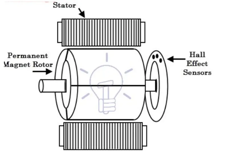
Hall effect sensor provides the information to stator armature excitataion with rotor position.