Week -2
SIMULINK MODEL FOR DOORBELL AND THERMISTOR
AIM:-
1) To a model of solenoid circuit for a DoorBell using Simulink Blocks.
2) To Model a thermostat controlled fan using simulink blocks.
STUDY 1:-
To Make a model of solenoid circuit for a DoorBell using Simulink Blocks.
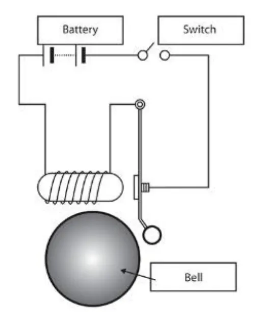
SIMULINK BLOCKS DIAGRAM FOR DOORBELL:-
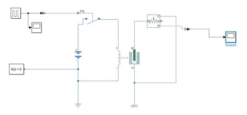
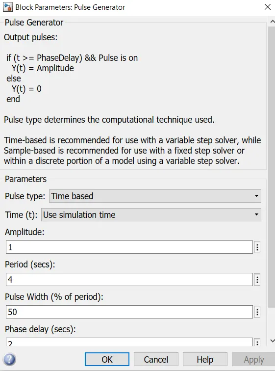
PARAMETER OF PULSE GENRATOR:-
SIMULINK MODEL EXPLANATION:-
We have used following model in the blocks-
1. Pulse Generator
2. Switch
3. Battery
4. Solenoid
5. Ideal Traslational Motion Sensor
6. Mechanical Traslational Sensor
7. Electrical Refrence.
8. Scope
As per given conditions switch is a close for a 2 seconds and released.
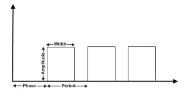
The pulse generator is used for to create square wave pulses at regulalr intervals , the block waveform parameters amplitude, pulse width ,period and phase delay determine shape of waveform.
WORKING-
- Signal source is connected with the switch .
- a battery is connected with the solenoid .
- solver block is simplify physical condition at the switch.
- Electrical refrence is given for the battery.
- Solenoiad plunger is connected with ideal motion sensor which is connected with scope block.
- P-S Converter and Vice-Versa is used whenver needed.
INPUTS-
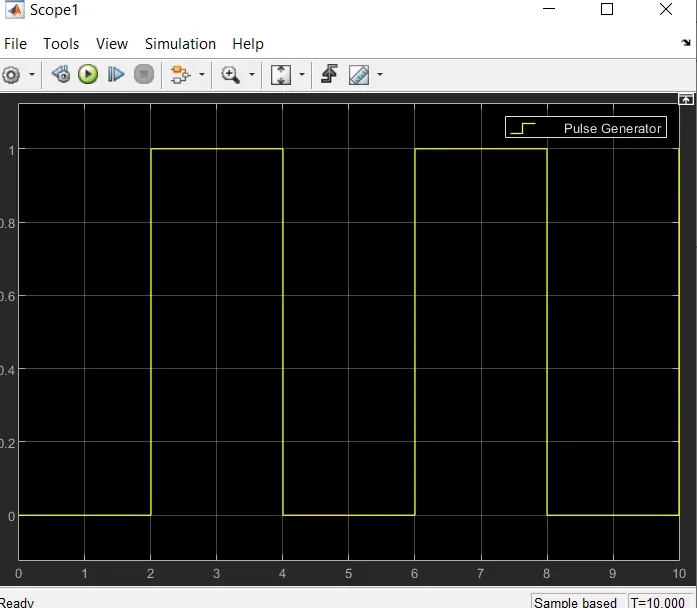
OUTPUTS:-
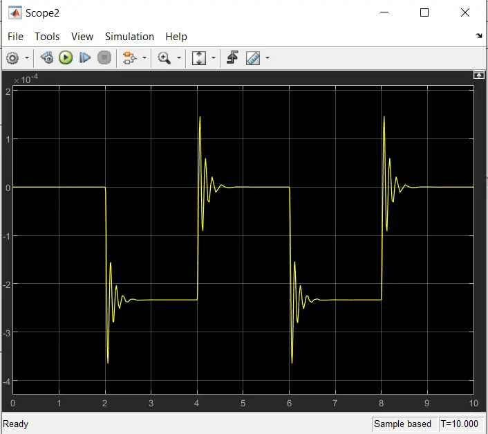
CONCLUSION-
Physical movement of the plunger is observes by using Ideal Traslational Motion Sensor and physical output is converted into simulink output model is displayed in the scope . by reducing spring constant value and increasing the damping valur vibrations will be reduced .
STUDY 2:-
To Model a thermostat controlled fan using simulink blocks.
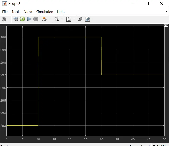
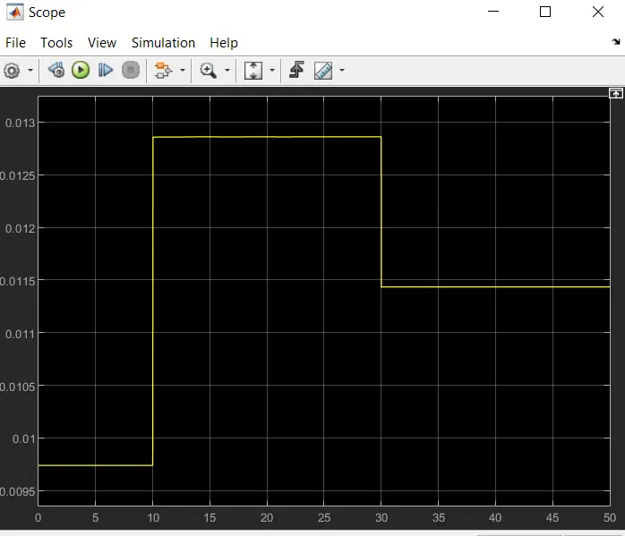
Conditions- temperature source must be kept at 0 to 20 degree for 10 sec. 27 degree for next 20 sec. and 23 degree celsius for next 20 sec. and the total cycle is 50 sec.
The threshold value for the thermostat should be 25 degree celsius.
MODEL:-
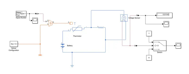
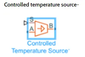
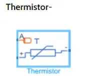
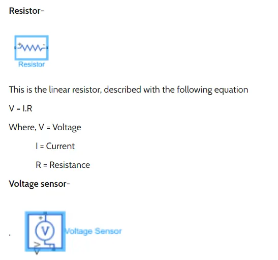
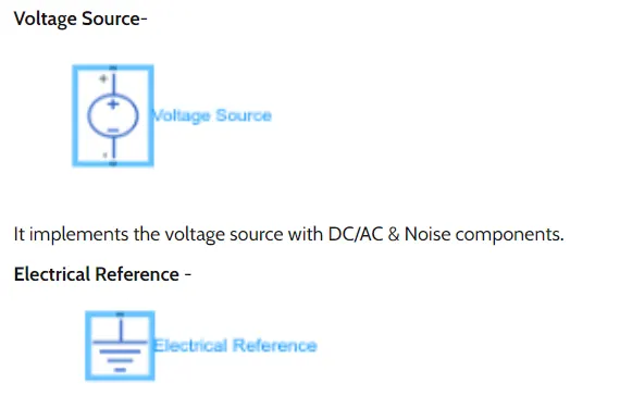
We have used following model in the blocks-
WORKING:-
- The sensor is connected with a variable heat source .
- A Batttery source is provided to the heat sensor.
- A Votage sensor is connected to the thermostat circuit for measuring the change in voltage.
- the output voltage of the sensor is connected with a switch as a refrence .
- the switch is connected with the current source for DC Motor.
- the ouput for the DC motor is connected with the ideal rotation mottion sensor. which is conncted with a scope block.
INPUTS:-
OUTPUTS:-
CONCLUSION:-
we are able to switch on the fan at a particular temperature.