Week-7 Challenge: DC Motor Control
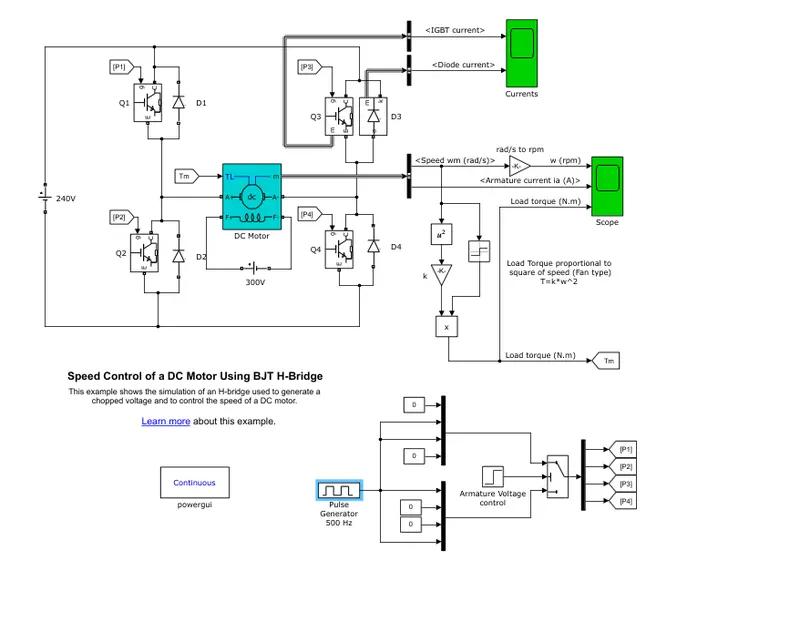
1. A. Explain a MATLAB demo model named ‘Speed control of a DC motor using BJT H-bridge’.
B. Comment on the armature current shoot-up from the scope results.
C. Refer to the help section of ‘The Four-Quadrant Chopper DC Drive (DC7) block’. Compare it with the H-bridge model.
Ans-
A-
The Bipolar Junction Transistor (BJT) when used for power switching applications, operates as an IGBT. When it is conducting (BJT operating in the saturated region), a forward voltage Vf is developed between collector and emitter (in the range of 1 V). Therefore, the IGBT block can be used to model the BJT device.
The IGBT block does not simulate the gate current controlling the BJT or IGBT. The switch is controlled by a Simulink signal . The DC motor uses the preset model (5 HP 24V 1750 rpm). It simulates a fan type load (where Load torque is proportional to square of speed). The armature mean voltage can be varied from 0 to 240 V when the duty cycle (specified in the Pulse Generator block) is varied from 0 to 100%.
The H-bridge consists of four BJT/Diode pairs (BJT simulated by IGBT models). Two transistors are switched simultaneously: Q1 and Q4 or Q2 and Q3. When Q1 and Q4 are fired, a positive voltage is applied to the motor and diodes D2-D3 operate as free-wheeling diodes when Q1 and Q4 are switched off. When Q2 and Q3 are fired, a negative voltage is applied to the motor and diodes D1-D4 operate as free-wheeling diodes when Q2 and Q3 are switched off.
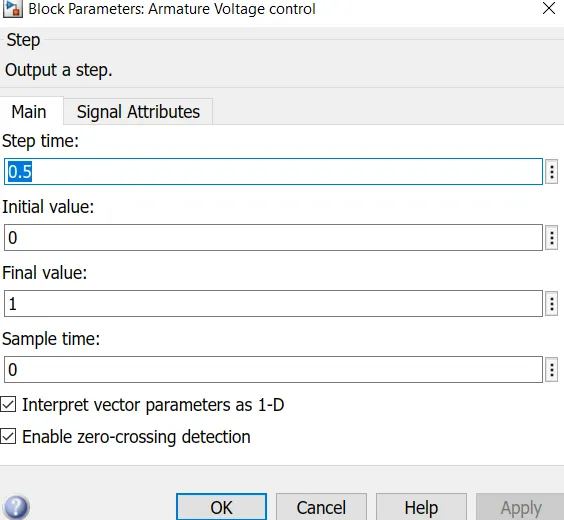
The motor starts in the positive direction with a duty cycle of 75% (mean DC voltage of 180V). At t= 0.5 sec., the armature voltage is suddenly reversed and the motor runs in the negative direction.
'Scope' shows motor speed, armature current and load torque and 'Currents' shows currents flowing in BJT Q3 and diode D3.
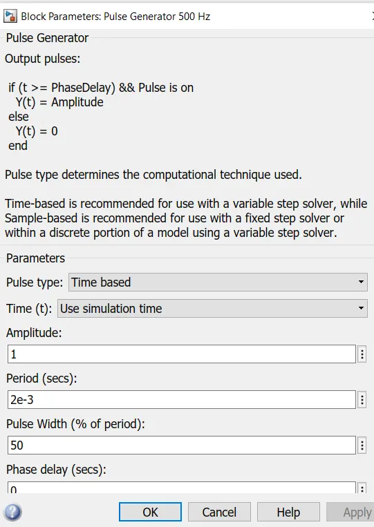
We can change the duty cycle value by clicking the pulse generator block,and vary the armature voltage from the armature voltage control.
in armature voltage controll we can change the step time ,intial valuee and the final value.
We can see the results of this configuration,
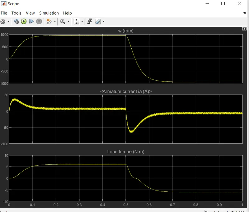
We can change the duty cycle from the pulse generator,by default we can see that the model runs at 75% duty cycle,and we can see the initial shoot up of the armature current after .5 seconds,so same effect can be seen in the negative axis also,for reducing the intial shoot up we have to check theOther value for the duty cycle.
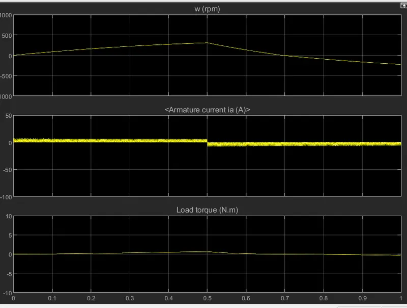
So changing the duty cycle value to 50% we can see the variation in the graphs,we can see that the armature current shoot up is visible and after .5 seconds when the voltage is reversed there is also the shoot up is present so in order to reduce the shoot up we should decrease the duty cycle.
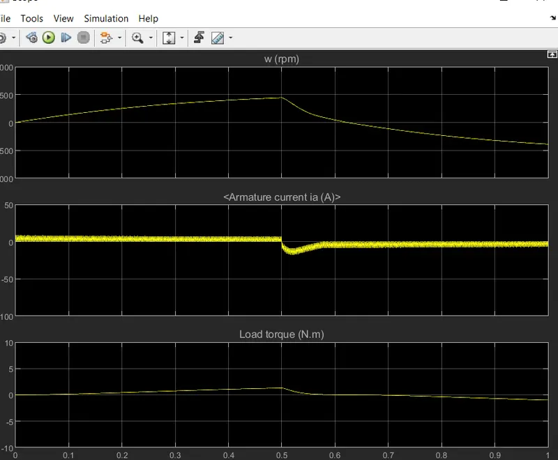
So when assigning 40% duty cycle we can see no shootup in the armature current it steadly goes around 10A and when the voltage is reversed it goea up to value of -10A.so the shoot up in the armature current is decreased when the duty cycle value is changed.
C. Ans-
4 quadrant chopper DC drives are used mainly due to their ability to work in the 4 different quadrants of operation. It allows the controller to command the DC motor to rotate in clockwise and counter clockwise directions and to perform braking. Traditional DC motors would rely on the innate friction and air resistance forces or actual physical brakes to bring the motor to rest. The other simpler option is to switch off the motor till it comes to rest.The 200 HP dc motor is separately excited with a constant 150 the V dc field voltage source. The armature voltage is provided by an IGBT converter controlled by two PI regulators. the converter is fed by a 515 V dc bus obtained by rectification of a 380 V AC 50 Hz voltage source. In order to limit the dc bus voltage during dynamic braking mode, a braking chopper has been added between The diode rectifier and The DC7 block.
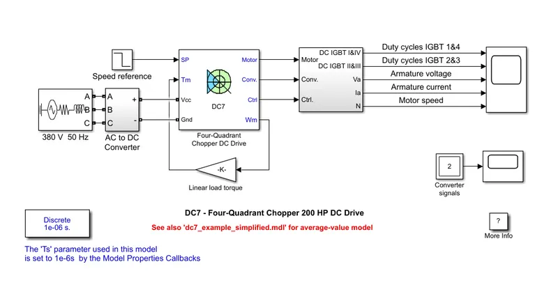
The first regulator is a speed regulator, followed by a current regulator. The speed regulator outputs The armature current reference (in p.u.) used by The current controller in order to obtain The electromagnetic torque needed to reach The desired speed. The speed reference change rate follows acceleration and deceleration ramps in order to avoid sudden reference changes that could cause armature over-current and destabilize The system. the current regulator controls the armature current by computing the appropriate duty ratios of The 5 kHz pulses of The four IGBT devices (Pulse Width Modulation). For proper system behaviour, the instantaneous pulse values of IGBT devices 1 and 4 are opposite to those of IGBT devices 2 and 3. This generates the average armature voltage needed to obtain the desired armature current. In order to limit the amplitude of the current oscillations, a smoothing inductance is placed in series with the armature circuit.
Both BJT H-bridges and four-quadrant choppers have benefits and drawbacks. H-bridges, such as the 4 quadrant choppers, can also stop without requiring air resistance, friction, or physical brakes to bring the motor to a halt. Automobiles use 4 quadrant DC choppers, whereas robotics and electromechanical devices use BJT H-bridges.
BJT H-bridges, unlike 4 quadrant DC choppers, cannot conduct regenerative braking, but they can perform dynamic braking. 4 quadrant DC choppers are beneficial in hybrid and electric automobiles because of this difference. The current signals in four quadrant DC choppers are disrupted to shift the direction of spinning of the motor. This is accomplished via a speed reference or a drive cycle, in which the speed values are translated to current signals, which are then interrupted to change the direction of the motor's spin. To change the direction of rotation of the motor, the polarity of the current is reversed (depending on the duty cycle) in BJT H-bridges.
In addition, the current signals in four quadrant DC choppers are chopped, which means they are not continuous but discontinuous, taking less time to simulate. . The current values in BJT H-bridges, on the other hand, are not chopped, implying that they are continuous and so require longer to simulate.
Finally, a PI controller is used to manage the speed and current in four quadrant DC choppers, although this is not done in the H-bridge.
2. Explain in a brief about operation of BLDC motor.
Ans-.Primary efficiency is a most importent feature for BLDC motors. Because the rotor is the sole bearer of the magnets and it doesn't require any power. i.e. no connections, no commutator and no brushes. In place of these, the motor employs control circuitry. To detect where the rotor is at certain times, BLDC motors employ along with controllers, rotary encoders or a Hall sensor.
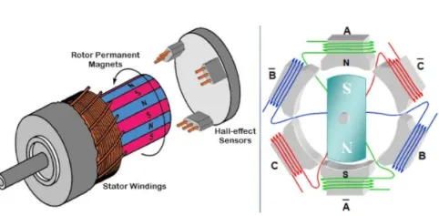
In this motor, the permanent magnets attach to the rotor. The current-carrying conductors are located on the stator. They use electrical commutation to convert electrical energy into mechanical energy.
The main design difference between a brushed and brushless motors is the replacement of mechanical commutator with an electric switch circuit. A BLDC Motor is a type of synchronous motor in the sense that the magnetic field generated by the stator and the rotor revolve at the same frequency.The Lorentz force law which states that whenever a current carrying conductor placed in a magnetic field it experiences a force. As a consequence of reaction force, the magnet will experience an equal and opposite force. In the BLDC motor, the current carrying conductor is stationary and the permanent magnet is moving.
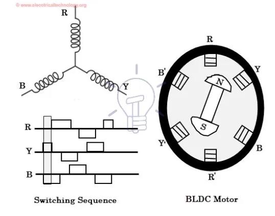
When the stator coils get a supply from source, it becomes electromagnet and starts producing the uniform field in the air gap. Though the source of supply is DC, switching makes to generate an AC voltage waveform with trapezoidal shape. Due to the force of interaction between electromagnet stator and permanent magnet rotor, the rotor continues to rotate.
With the switching of windings as High and Low signals, corresponding winding energized as North and South poles. The permanent magnet rotor with North and South poles align with stator poles which causes the motor to rotate.
Ans-
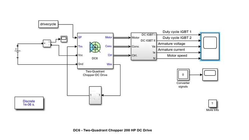
We have to create a two quadrant dc chopper so entering DC6 in the matlab we will get the model and we have to change the defalt model blocks, for our model we have to use different speed torque characteristics
Tm=0.0051ω2+24.7
To make this model we have to use math blocks in Simulink,from the torque output we are using a square block and it is connected to a gain block which we will assign value of 0.0051 .
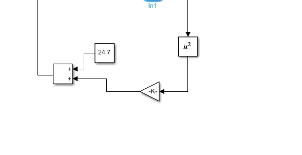
A constant block is made with value of 24.7 and add block is used to add these values.
Next we have to get the DC voltage source and it is given a 100V amplitude.
And this DC source is connected to current measurement block and the i terminal is connected to a scope.A drive cycle is made to connect to the speed terminal with 30 different values.30s is the period of the drive cycle.
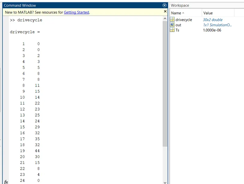
So we have modified the model with our own custom drivecycle and the model run time is 30 seconds.
results-
from the scope we can see the graphs,
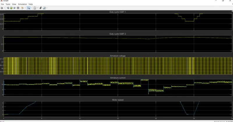
The motor speed has increased linearly from the start of 4 s and to the maximum level of 38 rad/s,it is at this point, that the maximum power is required by the motor to achieve this angular speed.From the max speed it is reduced from 20s and variation can be seen according to our drive cycle.
The armature voltage varies from -100V to 100V and the fluctuation can be seen in very small intervals and it continues upto the simulation is done,
The armature current have a sudden spike from the start of the simulation with a value of 10A,after 6s we can see the variation that is happening to the armature current,it increase a little steap and decreases after .2s and this fashion can be seen through the graph.after 18s the value of armature current decrease upto 2A. and it increases after 20s with minor variations.
Conclusions-
The two quadrant dc chopper model was created using Simulink and results were analysed.