Week -2
Aim-
1.To make a simulink model of a doorbell using given parameters
2.To make a simulink model of thermistor to sense the temperature of heater and regulate the fan using given parameters
Objective-
1.The doorbell simulink model consist of solenoid and where the switch is on for 2 seconds delay and then released.
2.The thermistor to the sense the temperature with given parameters which are temperature varies from
20 °C from 0 to 10 seconds, 27 °C from 10 to 30 seconds, 23 °C from 30 to 50 seconds
Fan conditions: ON if the temperature above 25 °C, OFF otherwise.
Introduction-
solenoid-
In simple terms, a solenoid converts electrical energy into mechanical work. The term is also often used to refer to a solenoid an integrated device containing an electromechanical solenoid which actuate valves, or a solenoid switch, which is a specific type of relay that internally uses an electromechanical solenoid to operate an electrical switch for example, an or linear solenoid.solenoid bolts, a type of electromechanical locking mechanism, also exist. In electromagnetic technology, a solenoid is an actuator assembly with a sliding ferromagnetic plunger inside the coil. Without power, the plunger extends for part of its length outside the coil; applying power pulls the plunger into the coil.
the basic components of the model are ,battery ,switch ,solenoid,and a bell with plunger.
model-
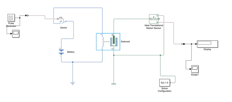
explanation-
the solenoid block is the main part of this model and for getting components for the doorbell model,we have accesed these blocks from the library,a battery block is connected to the solenoid and a switch is connected to the battery,
for creating the signal ,pulse generator is used,the input signal is converted to physical signal by using simulink ps convertor block.The provided physical signal must be greater than the threshold of the switch, for the switch to be closed or else it will be opened.
for representing the earthing of the circuit,a electrical reference is given to the path between the solenoid and the battery.
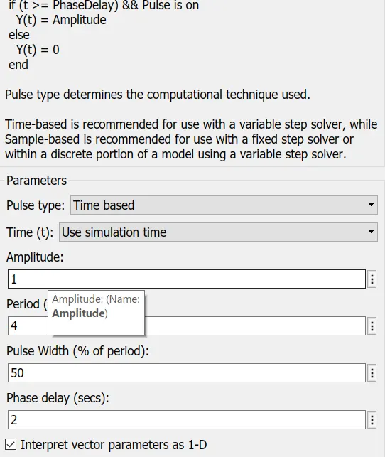
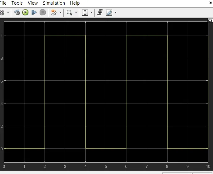
for providing the physical signal,we are change the values in the pulse generator block .in the figure the amplitude is unchanged,and we changing the period for 4,and we giving a value of 2 for the phase delay This means that initially the pulse will be zero and at 2 secs the pulse width will half of periods, so for the next two seconds the pulse will be at amplitude 1 only, then it will again come down to zero at 4th second and then it will at zero for next 2 secs thus completing the periods of 4 seconds.
the solenoid block have variable C and R which represents the plunger point and fixed point respectively.this R is connected to the R of the ideal translational sensor,which sense the position of the plunger and gives the output.
In ideal translational motion sensor,the V and P represents the velocity and position of the plunger,we need the position of the plunger.‘C’ in the Ideal Translational Motion Sensor block represents the mechanical translational conversion port which means that the mechanical process starts from ‘R’ and ends at ‘C’ and it again starts from ‘R’ and the cycle goes on.
so similarly we have to give a mechanical reference which represents a rigid block clamped so a mechanical reference is added,so C of the solenoid block is connected to the mechanical reference,
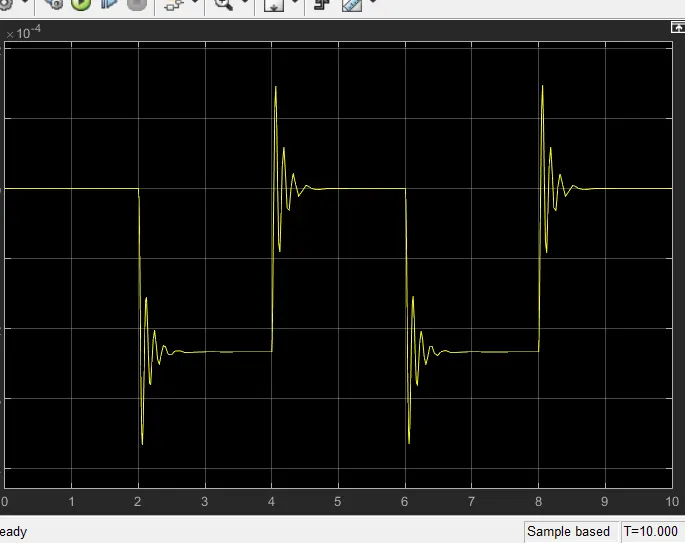
so the output signal is a physical signal and is converted by ps simulink convertor and it is connected to scope block which the graphical representation can be seen. then by giving run for the model we can see the graph as a result,
2.Model of thermistor to sense the temperature of heater and regulate the fan
Introduction-
Thermistor-The term thermistor comes from “thermal” and “resistor”. A thermistor is a type of resistor whose resistance is reliant on temperature; it’s a resistance thermometer. They’re made from metallic oxide which is moulded into a bead, disk, or cylindrical shape and then enclosed with epoxy or glass. There are two types of thermistors – the most commonly used is the Negative Temperature Coefficient (NTC) thermistor. The NTC’s resistance decreases as the temperature increases, and vice versa. With the Positive Temperature Coefficient (PTC) thermistor, the resistance increases as the temperature increases, and vice versa; it’s normally used as a fuse.Thermistors are easy to use, relatively cheap, and durable. They’re commonly used in digital thermometers, in vehicles to measure oil and coolant temperatures, and in household appliances such as ovens and refrigerators and are preferred for applications that require heating or cooling protection circuits for safe operation.
The basic components for this model is thermistor,signal builder,controlled temperature sensor,switch,scope.
the signal builder is used to provide input signal according to the given condition ,the graph has value with temperature and time we convert the temperature from celcius to kelvin(K),
for the first condition from 0 to 10 seconds the temperature is 293.15K and from 10 to 30 s the temperature changes to 300.15K and from 30 to 50 the temperature is decreased to a value of 296.15K.
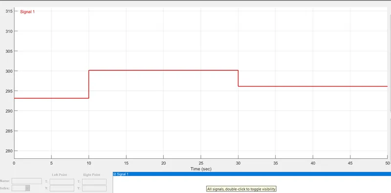
the signal buider is a block which produces a output based on the given condition we have given parameters to the signal tab and a signal is generated,
from the pulse generator the it is connected to simulink ps convertor which will convert it into a physical signal,after this signal is sent to the controlled temperature source block.This block represents an ideal energy source in a thermal network that can maintain a controlled temperature difference regardless of the heat flow rate. The temperature difference is set by the physical signal port S. A positive temperature difference causes the temperature at port B to be greater than the temperature at port A.
A thermal reference given in this path from the port b it is connected to the thermistor,the positive end of the thermstor is connected to the positive terminal of a 12v dc source.and the other terminal is connected to a resistor with 1 ohm resistance. and a voltage sensor block is connected in this path,The voltage sensor block is a representation of an ideal voltage sensor, which is a device that transforms voltage measured between two points in an electrical circuit into a physical signal proportional to the voltage.Connections + and - are conserving electrical ports through which the sensor is connected to the circuit. Connection V is a physical signal port that outputs voltage value.
This physical signal is converted by ps simulink convertor block.the centre port of Switch block is connected to output of PS-Simulink Converter which gives the voltage values. The top port of the Switch block is connected to a Constant block of value 1 and bottom port of the Switch block is connected to another Constant block of value 0.A threshold value is given to the switch tha the switch will be on when the temperature is above 25'c and the value will be 1 .and for 0 value the fan will be in off condition,a scope block is also given to analyse the graph
results-
scope 1
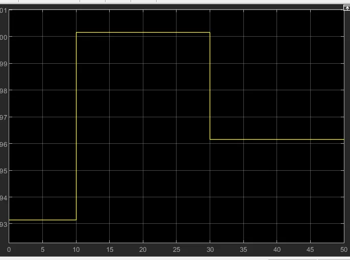
conclusion-
-both the models were created successfully by simulink software