Week-7 Challenge: DC Motor Control
Speed control of DC motor using BJT H-bridge:-
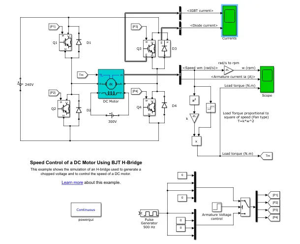
In this model the speed of DC motor is control by the IGBT semiconductor device. The Bipolar junction transistor operate as an IGBT. When the IGBT start the conducting the voltage that is forward voltage appear across the emitter and collector region in range of 1V.
By connecting the four IGBT the H-bridgr circuit is formed. The H-bridge consist of four IGBT such as (Q1 , Q2 , Q3 , Q4) and the four diode such as (D1 ,D2, D3, D4) and the DC motor connect such manner that the H-bridge is form.
Working of simulation:-
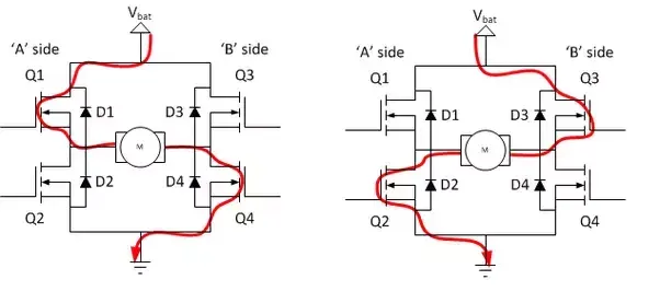
In these simulation the four IGBT is use which work as switch. The two swith operate at a time Q1 and Q4 or Q2 and Q3. When Q1 and Q2 are geting a fired signal from pulse generator the positive voltage are applied acrosss the motor and D3,D2 are free wheeling diode when Q1 and Q2 switch off. Similarly when Q2 and Q3 are fired then the the negative voltage appear across motor and diode D1 and D4 are free wheel diode operate when Q2and Q3 switch off.
Simulation result:-
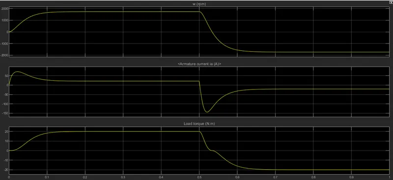
1) In the result as wee see in below image the graph of speed of motor , armature current , load torque. In armature current graph, the armature curent at start of motor is shhot from 0 to bove 50 due the pole reversing.
2) At 0.5 sec, the the voltage of motor are reversed so the motor run in negative direction. As we see load torque graph, the reversing voltage across motor the torque intially at approx 6 Nm but the due to reversing the negative trque of same magniture is observed.
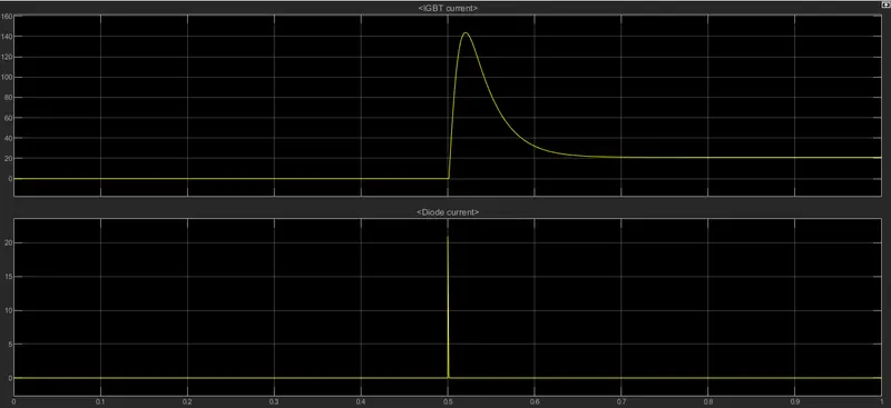
The graph of IGBT current and diode connecting to IGBT:- The scope coonect across Q3 so the condition of Q3 is appear in graph upto 0.5 the Q3 is not fired but at 0.5 Q3 is getting fire signal and start conducting a current .
B) For quadrant chopper of DC drive block :-
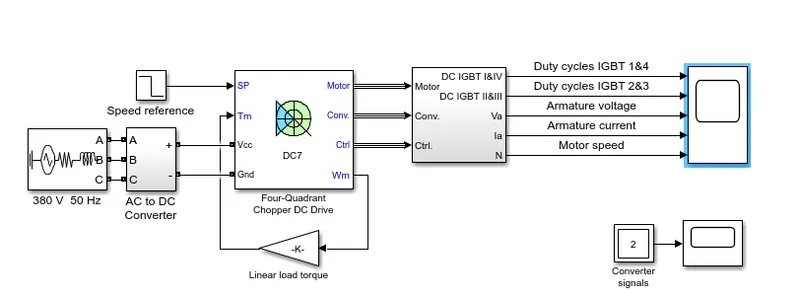
In these model the motor is used with constant 150V DC field voltage source. The armature voltage is provided by an IGBT converter controlled by two PI controller.The converter is fed by 515V DC bus obtained by rectification of a 380V AC 50Hz.In order to limi the DC bus voltage in braking mode, a braking chopper is added betwen diode rectifier and DC7 block.
The speed regulator follow by current regulator.The current regulator control the armature current by appropriate duty ratio of 5KHz pulse for 4 IGBT device. For proper system behaviour, the IGBT device 1 and 4 are the opposite to IGBT 3 and 2. these generated average voltage needed to obtainthe desired armature current
comparison with H-bridge:-
1) As we see the above block simulation, the DC7 is capable of operating in all 4 quadrant of motoring application such as forward braking ,forward motoring, reserve motoring,reserve braking . A motor operate in two mode such as motoring and braking . th emotor capable of operating in both direction of rotation and of producing both motoring and regeneration is called a four quadrant variable speed drive.
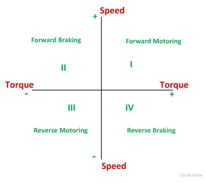
2) In motoring mode, the machine work as a motor and convert the electrical in mehanical energy supporting its motion.In braking mode,the machine work as generatorand convert mechanical energy into electrical energyand result it oppose the motion.The motor can work in both,forward and reverse direction that is motoring and braking operation.
3) In the I quadrant power developed is positive and the machine is working as a motor supplying mechanical energy. The I (first) quadrant operation is called Forward Motoring. II (second) quadrant operation is known as Braking. In this quadrant, the direction of rotation is positive, and the torque is negative, and thus, the machine operates as a generator developing a negative torque, which opposes the motion.
4) The kinetic energy of the rotating parts is available as electrical energy which may be supplied back to the mains. In dynamic braking, the energy is dissipated in the resistance. The III (third) quadrant operation is known as the reverse motoring. The motor works, in the reverse direction. Both the speed and the torque have negative values while the power is positive.In the IV (fourth) quadrant, the torque is positive, and the speed is negative. This quadrant corresponds to the braking in the reverse motoring mode.
H-bridge :- An H-bridge is a simple circuit which control DC motor forward and backward. In H-bridge if we close switch 1 and 4 as same in image then the motor connect across voltage and motor start rotating in one direction. If the switch 2 and 3 switch as same in image then the motor connect acorss reverse polarity of supply then motor rotate reverse direction.
2) EV model using a DC7 block:-
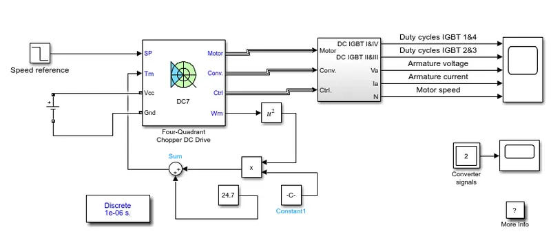
In the below model of EV by using a DC7 block, some modification some block are as follows:-
Modifying the energy source :- The simple DC source is used to provide DC supply the DC 7 block.
Vehicle load characteristic :- The linear block replace by system according to load characteristic. These system take the input from motor block and calculate the output.
T= 24.7 + 0.0051W^2
Result:-
3) Opration of BLDC motor:-
BLDC motor works on the principle similar to that of a Brushless DC motor. The Lorentz force law which states that whenever a current carrying conductor placed in a magnetic field it experiences a force. As a consequence of reaction force, the magnet will experience an equal and opposite force. In the BLDC motor, the current carrying conductor is stationary and the permanent magnet is moving.
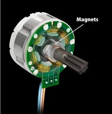
When the stator coils get a supply from source, it becomes electromagnet and starts producing the uniform field in the air gap. Though the source of supply is DC, switching makes to generate an AC voltage waveform with trapezoidal shape. Due to the force of interaction between electromagnet stator and permanent magnet rotor, the rotor continues to rotate.
With the switching of windings as High and Low signals, corresponding winding energized as North and South poles. The permanent magnet rotor with North and South poles align with stator poles which causes the motor to rotate.
Advantage of BLDC motor:-
- Less overall maintenance due to absence of brushes
- Reduced size with far superior thermal characteristics
- Higher speed range and lower electric noise generation.
- It has no mechanical commutator and associated problems
- High efficiency and high output power to size ratio due to the use of permanent magnet rotor
- High speed of operation even in loaded and unloaded conditions due to the absence of brushes that limits the speed
- Smaller motor geometry and lighter in weight than both brushed type DC and induction AC motors.
- Long life as no inspection and maintenance is required for commutator system
- Higher dynamic response due to low inertia and carrying windings in the stator
- Less electromagnetic interference
- Low noise due to absence of brushes