Week 5 Battery characteristics using drive cycle
Working of Step for battery charge and discharge using UDDS data:-
To build a battery modelling of charge and discharge using UDDS data ,we have a two thing as follows:-
1. battery configuration 2. UDDS file
In battery configuration ,the battery are set to foolowing data : The battery use in modelling is Lithium-Ion
1. Nominal voltage:- 7.2V
2. Rated capacity:- 5.4Ah
3.Intial state of charge:-100
4. Maximum capacity:- 5.4V
5. Cut-off voltage :- 5.4V
6. fully charged voltage:-8.3807V , Nominal discharge current :-2.3478
7. Internal resistence :-0.013333 ohm, Capacity at nominal voltage :-4.8835Ah
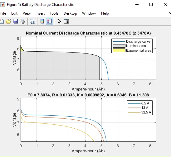
2.UDDS file:- the UDDS is urban dynamometer driving schedule. it contain data of speed of vehicle v/s time.
3.signal builder block:- In this model the signal buillder block are used to create drive cycle data of UDDS cycle but the UDDS data having content in speed v/s time and signal builder block need the data in current form . so speed v/s time data is converted into current v/s time . then signal builder block start to build block. the output of signal builder block is connected to the current controlled source.
4.current controlled source:- this block is used to convert simulink input signal into an equivalent current source .the generated current is due to input signal of the block.
5.scope :- this is used to display the waveform of state of charge ,voltage and current.
6. bus selector :- bus selector is used to obtain input signal from battery and gives output to scope. it is transferring media for differnt path or bus.
7. powergui:- the powergui block is used to simulate any simulation in simscape electrical .it stored simulink circuit to state space equation of model.
Step to build a model of battery charge discharge by using UDDS data:-
signal builder block connected to current controlled source terminal and negative of this source connected to positive terminal of battery and positive terminal of source connected to negative of battery and output of battery connected to bus selector..output of bus selector is given to scope..
Result :- battery model ofcharge and discharge by using UDDS data
1. In this simulation , we obtain a three graph state of charge ,voltage and current
2. From state of charge graph represent the battery is intially charge at 100% after the load as drive cycle the battery start to discharge and curve of SOC goes down.
3. The current graph represent the discharging and charging state of various load condition . At positive value battery charge and at negative value battery discharge .
4. voltage curve are also varry with the load demand .