Week-7 Challenge: DC Motor Control
Aim :
DC Motor Control
Objective :
1. A. Explain a MATLAB demo model named ‘Speed control of a DC motor using BJT H-bridge’.
B. Comment on the armature current shoot-up from the scope results.
C. Refer to the help section of ‘The Four-Quadrant Chopper DC Drive (DC7) block’. Compare it with the H-bridge model.
2. Develop a 2-quadrant chopper using Simulink & explain the working of the same with the relevant results. (Refer to the article - Multiquadrant operation of the motor )
3. Explain in a brief the operation of the BLDC motor.
# First Objective :
- A. Explain 'Speed control of a DC motor using BJT H-bridge’ demo model
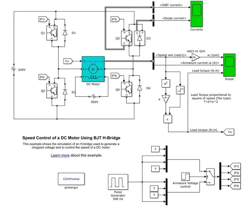
This model is consists of an H bridge with 4 BJT - Diode Pair. The inputs such as duty cycle and the step time are given from the pulse generator block, armature voltage-current block.
This H bridge is made up of four switches Q1, Q2, Q3, Q4, and four diodes D1, D2, D3, D4. As IGBT can be used as a switch which can be either in off or on position. When the motor is coasting it generates electricity due to its flexibility.
IGBT block :
The IGBT block implements a semiconductor device controllable by the gate signal. The IGBT is simulated as a series combination of a resistor Ron, inductor Lon, and a DC voltage source V, with a switch controlled by a logical signal (g > 0 or g = 0).
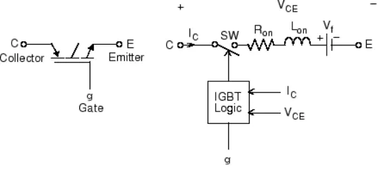
The IGBT turns on when the collector-emitter voltage is positive and greater than Vf and a positive signal is applied at the gate input (g > 0). It turns off when the collector-emitter voltage is positive and a 0 signal is applied at the gate input (g = 0).
Diode :
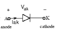
The diode is a semiconductor device that is controlled by its own voltage Vak and current Iak. When a diode is forward biased (Vak > 0), it starts to conduct with a small forward voltage Vf across it. It turns off when the current flow into the device becomes 0. When the diode is reverse biased (Vak < 0), it stays in the off state
Different Modes of Available :
- If switch Q1 and Q4 is closed, this will cause the current to flow from the source, through switch 1 and then through the load, then through switch 4, then down to the ground, this is the forward motion of the motor.
- If switch Q2 and Q3 is closed, this will cause the current to flow from the source, through switch 3 and then through the load, then through switch 2, then down to the ground this is Reverse the motion of the motor.
- if switch Q1, Q3 OR Q2, Q4 is closed, then both sides of the motor have no potential difference and this is called brake mode
- if switch Q1, Q2, or Q3, Q4 is closed then it will cause a short and burn out the H-bridge.
- if only one switch or none switch is closed in this state the motor will be just coasting.
Working of the model :
- The DC motor uses the preset model (5 HP 24V 1750 rpm). It simulates a fan-type load. The armature means voltage can be varied from 0 to 240 V when the duty cycle(specified in the pulse generator block) is varied from 0 to 100%
- the H-bridge consists of four BJT/Diode pairs (BJT Simulated by the IGBT models).
- two transistors are switched simultaneously: Q1 and Q4 or Q2 and Q3. When Q1 and Q4 are fired,a positive voltage is applied to the motor and the diodes D2-D3 operate as free wheeling diodes when Q1 and Q4 are switched off
- when Q2 and Q3 are fired a negative voltage is applied to the motor the diodes D1-D4 operate as free wheeling diode when Q2 and Q3 are switched off
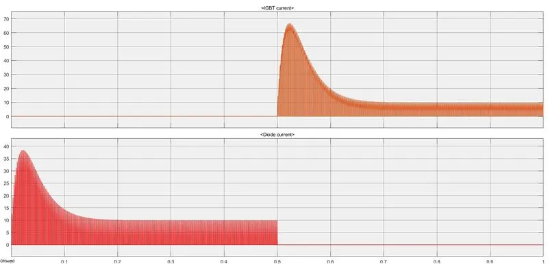
The above graph shows the current passing through IGBT and diode so for 0 - 0.5 sec current is flowing through the diode D3 and 0.5 to 1 sec the current is passing Q3.
here Load torque is proportional to the square of angular velocity.
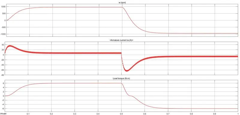
the above plot shows that at the beginning of the cycle there is a sudden peak in the armature current, the same repeat in the opposite direction when the motor rotates in the opposite direction.
B. comment on the armature current shoot-up from the scope results.
As the principle of pulse width modulation (PWM)
The average value of the voltage (and current ) fed to the load is controlled by turning the switch between supply and load on and off at a fast rate. The PWM switching frequency has to be high enough not to affect the load, which is to say that the resulting waveform perceived by the load must be smooth as possible.
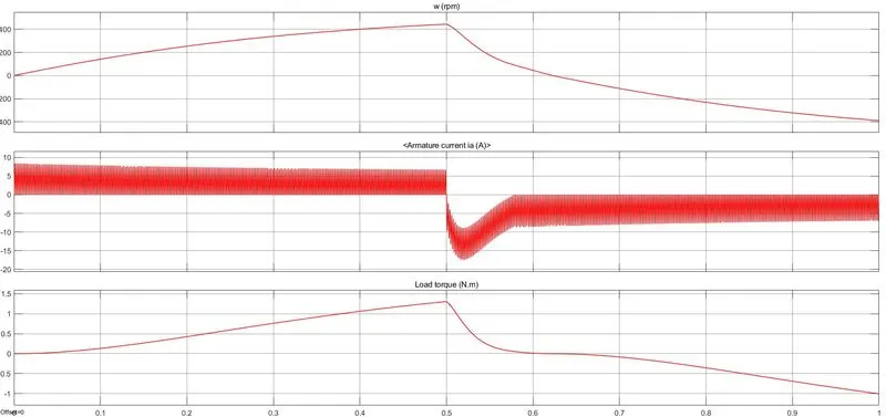
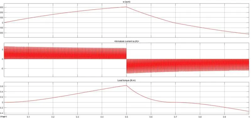
The peaks can be removed by reducing the duty cycle.
initial value :
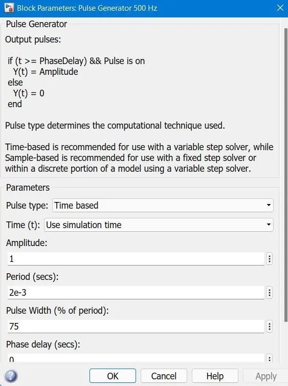
initially, the duty cycle is 75 %
The following plot shows the output when the pulse width value is changed 50%
As there is a peak when the motor is switching the directions, the duty cycle is future to 40% and the following plot shows the output:
C.Refer to the help section of ‘The Four-Quadrant Chopper DC Drive (DC7) block’. Compare it with the H-bridge model.
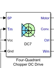
The Four-Quadrant Chopper DC Drive (DC7) block represents a four-quadrant, DC-supplied, chopper (or DC-DC PWM converter) drive for DC motors. This drive features closed-loop speed control with a four-quadrant operation. The speed control loop outputs the reference armature current of the machine. Using a PI current controller, the chopper duty cycle corresponding to the commanded armature current is derived. This duty cycle is then compared with a sawtooth carrier signal to obtain the required PWM signals for the chopper.
The main advantage of this drive, compared with other DC drives, is that it can operate in all four quadrants (forward motoring, reverse regeneration, reverse motoring, and forward regeneration). In addition, due to the use of high switching frequency DC-DC converters, a lower armature current ripple (compared with thyristor-based DC drives) is obtained. However, four switching devices are required, which increases the complexity of the drive system.
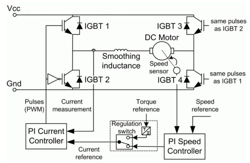
The machine is separately excited with a constant DC field voltage source. There is thus no field voltage control. By default, the field current is set to its steady-state value when a simulation is started.
The armature voltage is provided by an IGBT converter controlled by two PI regulators. The converter is fed by a constant DC voltage source. Armature current oscillations are reduced by a smoothing inductance connected in series with the armature circuit.
Working of Four Quadrant chopper:
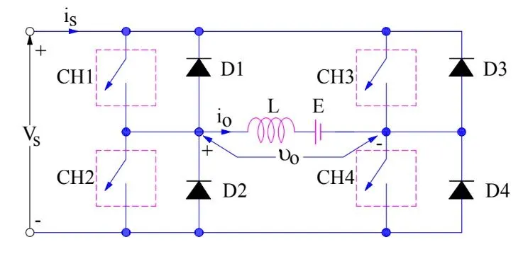
First quadrant operation :
CH1 is in operating condition, CH1 and CH4 are ON, CH2 and CH3 are OFF the load directly connected to the source hence the Vo = Vs .it may be noted that current flows from source to load by the direction Io.
CH1 is OFF the load current freewheels through CH4 and D2. During this period load voltage and current is positive
Second quadrant operation :
CH2 is operated condition, CH2 is ON and CH3, CH1, CH4 is OFF condition. CH2 is ON load drives the current through CH2, D4, L.inductor stores the energy during the CH2 is ON condition.
CH2 is OFF the current feedback to the source through the D4, D1. It should be noted that at this point (E+Ldi/dt) is more than Vs. As load voltage is positive and current is negative
Third quadrant operation :
CH3 is in operating condition, the polarity of E emf is reversed to have the third quadrant operation. CH3, CH2 is ON load, and CH1, CH4 is OFF, get connected to the source hence Vo=Vs. Current flows from source to load due to the change in polarity of the emf current and voltage is negative.
CH3 is OFF negative load current freewheels through the CH2 and D4.In this manner, Vo and Io is negative hence chopper operated in the third quadrant
Fourth quadrant operation :
CH4 is operated while keeping CH1, CH2, and CH3 OFF. The polarity of load E emf needs to be reversed like the third quadrant. CH4 is ON positive current flows from CH4 through the D2 and L. Inductance store the energy during CH4 is ON.
CH4 is made OFF, the current feedback from the source to the load, and the current is positive while voltage is negative. This lead chopper to operate in the fourth quadrant and acts as a step-up chopper
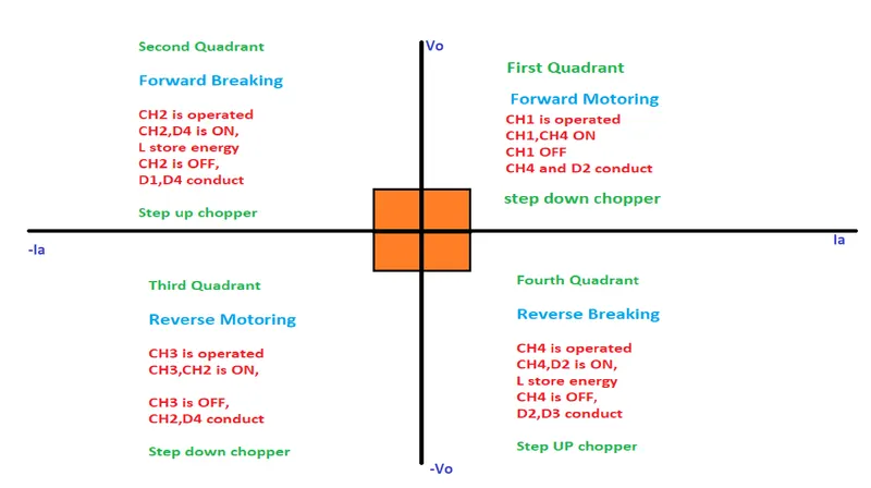
Comparison of Four quadrant chopper and BJT H bridge :
1.the 4 quadrants work in all four modes like
- forward motoring
- forward breaking
- reverse motoring
- reverse breaking
but the BJT H bridge work on only two modes
- forward motoring
- reverse motoring
2. to change the direction of the motor from forward to reverse and vice versa, the current signal transited from one signal to another switch while in the H bridge model, the direction of rotation of the motor is changed by the polarity of the motor
3. four-quadrant chopper having a high switching frequency while the H bridge has a low switching frequency.
4. the armature current in the four-quadrant chopper have a little spike at the transition from one to other switches because of high switching frequency while the H bridge has a high spike of current.
5.four-quadrant chopper is generally used in industrial applications while the H bridge model is used in robotics
# Second objective :
Develop a 2-quadrant chopper using Simulink & explain the working of the same with the relevant results.
2 quadrant chopper circuit :
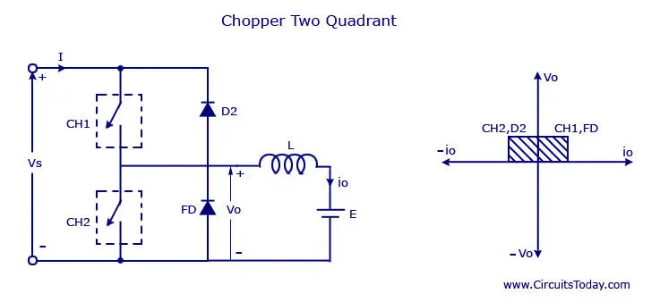
for First quadrant/motoring mode:
Here in the above circuit when switch CH1 is ON and CH2 OFF, Vs equal to Vo current flow from source to the load, and the inductor stores the energy.CH1 is the OFF inductor that releases the energy through the FD diode. where the Vo and Io are positive.
for Second quadrant/ regenrative mode :
CH2 is ON, the load current is negative it flows through CH2. where Vo is zero.
CH2 is OFF, the current flows from load to the source through the D2 diode. where (E+Ldi/dt) greater than Vs, at that point current is negative and voltage is positive.
Simulink model for 2-quadrant chopper:
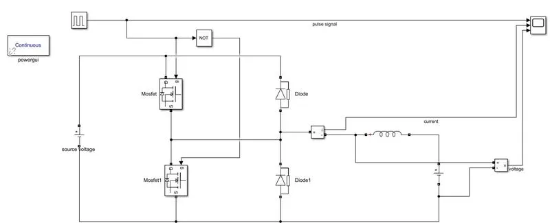
Here in the above model, we used MOSFET and diode as shown above model.
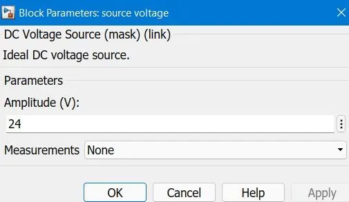
and DC voltage source is of 24 Volt is used.
get series RLC block is used and select L to get the inductor. the blockwork as load.
for considering motor load voltage source of 12 volts is connected with the inductor in series.
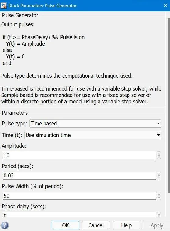
the pulse generator is used to get the switching condition and connected to the MOSFET. Two MOSFETs will not get the same switching condition NOT block is used.
To clearly see the voltage amplitude of 10 is entered and pulse width 50 % with a period as 0.02 sec.
input values :
Result :
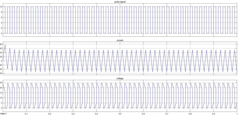
The above results are showing that the voltage is minimum zero and goes positive. the current goes negative and positive.
#Third Objective :
A brief about the operation of BLDC motor
A brushless DC motor consists of a rotor in the form of a permanent magnet and a stator in the form of polyphase armature windings. It differs from the conventional dc motor in such that it doesn’t contain brushes and the commutation is done using electrically, using an electronic drive to feed the stator windings.
Basically, a BLDC motor can be constructed in two ways- by placing the rotor outside the core and the windings in the core and another by placing the windings outside the core. In the former arrangement, the rotor magnets act as an insulator and reduce the rate of heat dissipation from the motor and operate at a low current. It is typically used in fans. In the latter arrangement, the motor dissipates more heat, thus causing an increase in its torque. It is used in hard disk drives.
- Outer Rotor
- Inner Rotor
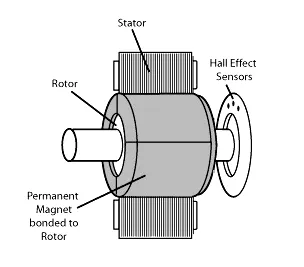
BLDC motor constructed with the stator as field winding and rotor with permanent magnet. Motor consists of The Hall effect sensors that are used to detect the position of the rotor are also used to detect speed by measuring the time it takes for the sensors to switch.
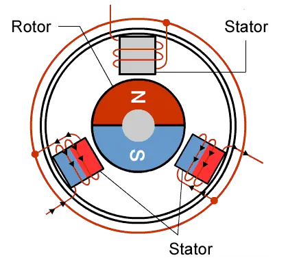
BLDC motor works on the principle similar to that of a Brushed DC motor. The Lorentz force law states that whenever a current-carrying conductor is placed in a magnetic field it experiences a force. As a consequence of the reaction force, the magnet will experience an equal and opposite force.
In figure 4 (A), the GREEN winding labeled “001” is energized as the NORTH pole, and the BLUE winding labeled as “010” is energized as the SOUTH pole. Because of this excitation, the SOUTH pole of the rotor aligns with the GREEN winding and the NORTH pole aligns with the RED winding labeled “100”. In order to move the rotor, the “RED” and “BLUE” windings are energized in the direction shown in figure 4(B). This causes the RED winding to become the NORTH pole and the BLUE winding to become the SOUTH pole. This shifting of the magnetic field in the stator produces torque because of the development of repulsion (Red winding – NORTH-NORTH alignment) and attraction forces (BLUE winding – NORTH-SOUTH alignment), which moves the rotor in the clockwise direction.
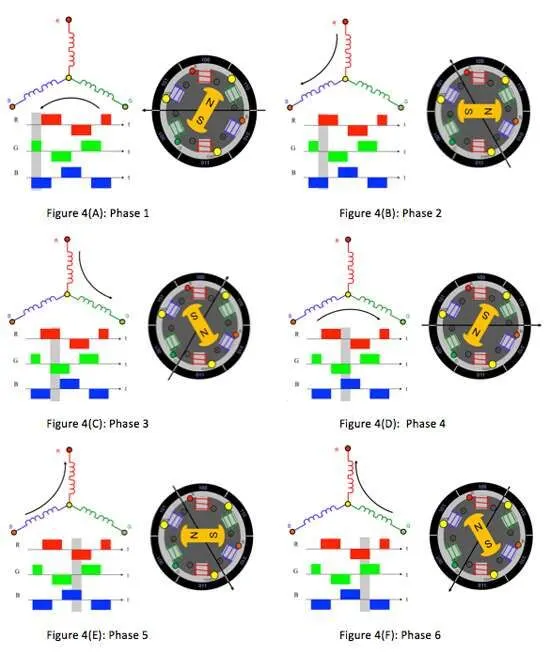
This torque is at its maximum when the rotor starts to move, but it reduces as the two fields align to each other. Thus, to preserve the torque or to build up the rotation, the magnetic field generated by the stator should keep switching. To catch up with the field generated by the stator, the rotor will keep rotating. Since the magnetic field of the stator and rotor both rotate at the same frequency, they come under the category of synchronous motor.
Brushless motors offer several advantages over brushed DC motors, including high torque to weight ratio, increased efficiency producing more torque per watt, increased reliability, reduced noise, longer lifetime by eliminating brush and commutator erosion, elimination of ionizing sparks from the commutator
Conclusion :
- we studied the ‘Speed control of a DC motor using BJT H-bridge’ model and comment on some results.
- we developed the two-quadrant Simulink model and explain the results.
- we briefly explain the operation of the BLDC motor.