Week -2
Aim :
- Make a Simulink model of Doorbell using solenoid block with the following details.
Objective :
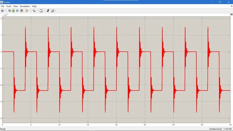
- Create a situation where the switch is closed for 2 seconds and then released. Observe the physical movement of the plunger.
code block :
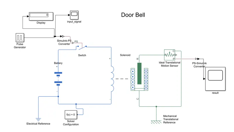
Model Explaination :
- Pulse generator
- display
- scope
- electrical switch
- battery
- solenoid
- ideal translation motion sensor
- electrical reference
- mechanical reference
- ps to simulink converter
- simulink to ps converter
- as per the given condition the switch should be closed for 2 second for that we used pulse generator
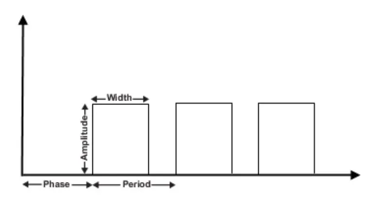
pulse width is %of period
- output generated by pulse generator
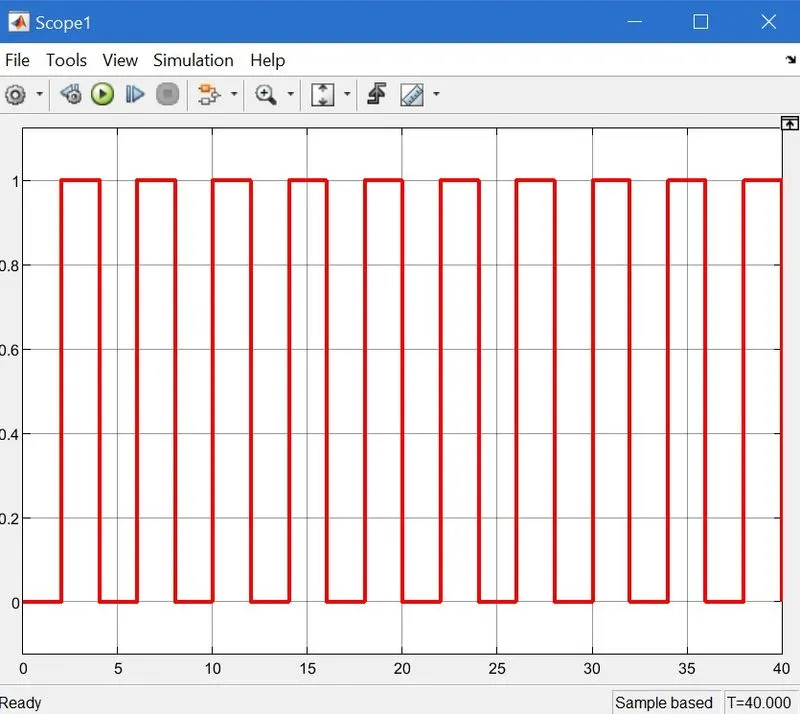
- pluse signal generated for 40 sec.
- that pulse signal passes to the electrical switch by converting the simulink signal to the physical signal as the as the input and threshold value at switch is greater than the input signal then switch is closed otherwise switch is open
- threshold value as i taken is 0.8.
- the circuit get complete when we connect the battery and solenoid to switch.
solenoid -
The Solenoid block represents the electrical characteristics and generated force for the solenoid in the following figure:
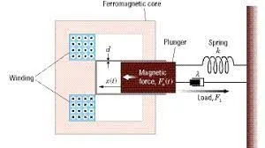
- when the switch is close the current flows through the solenoid which generate the force and moves the plunger.
to get the displacment and velocity of plunger ideal translation motion sensor is used.
- R and C port of sensor connected to the R and C port of the solenoid,and v port remain unconnected as we only need the position of plunger.
- P is connected to scope block to get result in between ps to simulink block is connected.
- mechanical reference connected to the c terminal of solenoid and electrical reference is connected to the - ve terminal of the battery also solver congiguration block connected the -ve terminal.
result :
second study :
Aim :
- Use a thermistor to sense the temperature of a heater & turn on or turn off the fan as per conditions
objective:
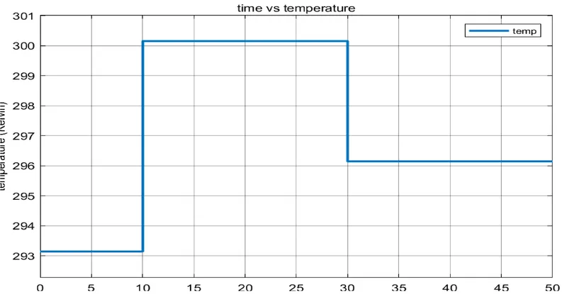
- Temperature source: 20 °C from 0 to 10 seconds, 27 °C from 10 to 30 seconds, 23 °C from 30 to 50 seconds
- Fan conditions: ON if the temperature above 25 °C, OFF otherwise
code block:
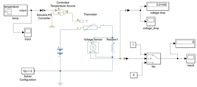
Model explaination :
- signal builder
- controlled temperature source
- thermistor
- resistor
- voltage sensor
- switch
- constant
- scope
- display
- simulink to ps converter
- ps to simulink converter
- signal builder in that we can generate any type of signal,by using signal builder we generated the temperature signal according to the given condition in the question.but in kelvin because of termistor required values in kelvin.
- that signals are passes to the temperature controlled source
This block represents an ideal energy source in a thermal network that can maintain a controlled temperature difference regardless of the heat flow rate. The temperature difference is set by the physical signal port S. A positive temperature difference causes the temperature at port B to be greater than the temperature at port A.
thermistor -
A thermistor is a type of resistor whose resistance is reliant on temperature.The working principle of a thermistor is that its resistance is dependent on its temperature. If we know the exact relationship between how changes in the temperature will affect the resistance of the thermistor – then by measuring the thermistor's resistance we can derive its temperature
thermistor's realtes with temperature also it depends on the material in which it is made.A negative temperature coefficient (NTC) thermistor will decrease it's resistance value when temperature increases whereas positive temperature coefficient will increase its resitance when temperature increases.
NTC is widely used in industries ,thermistor have high sensitivity which can be upto 10 % change per degree celcius and there typical response time is 0.5 to 5 sec.
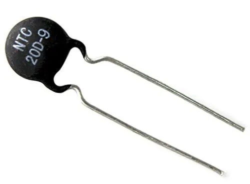
- the thermistor block shows NTC tempetaure and resistor relation it decreses the resistance as increase in temperature.
- for that we connect +ve terminal of the thermistor to the +ve terminal of the battery -ve to the -ve terminal of the thermistor in between reisistor is connect
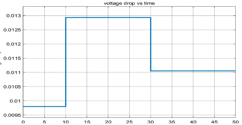
- using voltage sensor we get the volatge across the resistor
- switch block control the fan as if temperature is greater than 25 fans will on that mean voltage drop at the 25 degree celcius so if that value greater than threshold value fan ON otherwise off
- to see the result we use scope block.
voltage drop:
result:
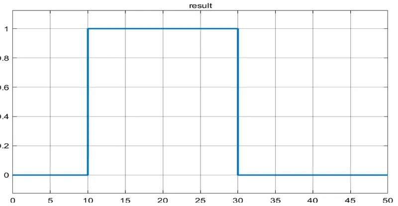
from 0-10 sec fan will OFF beacause temperature 293.15 K which is below 298.15 K ,then 10-30 fan will turn ON beacuse temperature 300.15 and 30-50 fan will turn OFF beacause temperature goes to 296.15k which is less than 298.15 K.
Also fan control motion can be get by using the DC Motor
code block :
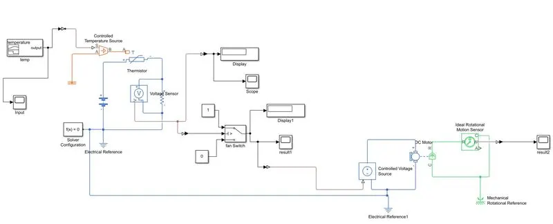
Model explaination :
all the block are same as the above study,just extra we use the DC Motor
- DC Motor
- controlled voltage source
- ideal rotational motion sensor
- Mechanical reference
all the ouput of the fan switch block is passes to controlled voltage source
what is the controlled voltage source block -
The block represents an ideal voltage source that is powerful enough to maintain the specified voltage at its output regardless of the current passing through it. The output voltage is V = Vs, where Vs is the numerical value presented at the physical signal port.
the +ve terminal of the block is connected to +ve terminal of the DC Motor and -ve terminal of controlled voltage source block is connected to the -ve terminal of DC Motor
The DC Motor block represents the electrical and torque characteristics of a DC motor.
R and C ports of the dc motor is connected to rotational motion sensor which gives the output as angular velocity and angle
we required only angular velocity we connected the scope block to the W port of ideal rotational sensor
which gives result as follows
result 2 :
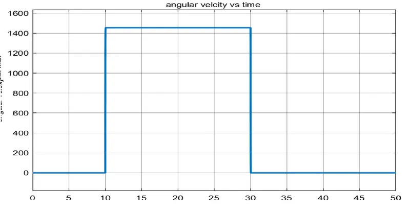
from 0-10 sec fan will OFF beacause temperature 293.15 K therefore angular velocity is 0 which is below 298.15 K ,then 10-30 fan will turn ON therefore angular velocity is increses then beacuse temperature 300.15 and 30-50 fan will turn OFF beacause temperature goes to 296.15k which is less than 298.15 K. this shows zero angular velcoty.
conclusion :
study shows the usage of solenoid in practical way and study 2 shows the thermistor usages in practical way
how it get affected as temperature increases or decreases.