Week-7 Challenge: DC Motor Control
Aim : -
1) A. Explain a MATLAB demo model named ‘Speed control of a DC motor using BJT H-bridge’.
- Comment on the armature current shoot-up from the scope results.
- Refer to the help section of ‘The Four-Quadrant Chopper DC Drive (DC7) block’. Compare it with the H-bridge model.
2) Develop a 2-quadrant chopper using Simulink & explain the working of the same with the relevant results. (Refer to article - Multiquadrant operation of motor)
3) Explain in a brief about operation of BLDC motor.
Solution: -
- Explain a MATLAB demo model named ‘Speed control of a DC motor using BJT H-bridge’.
- Comment on the armature current shoot-up from the scope results.
First we observe the model :
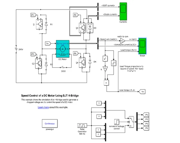
So, in the model there is use of some power electronic devices like bjt, diode and dc motor and h bridge circuit etc. So now we understand some basics of the components.
BJT
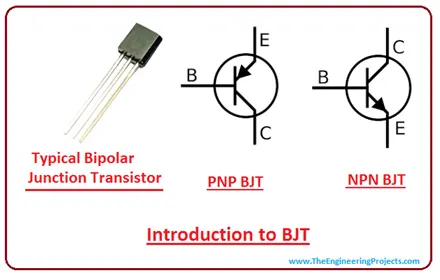
A bipolar junction transistor is a three-terminal semiconductor device that consists of two p-n junctions which are able to amplify or magnify a signal. It is a current controlled device. The three terminals of the BJT are the base, the collector, and the emitter. A signal of a small amplitude applied to the base is available in the amplified form at the collector of the transistor. This is the amplification provided by the BJT. Note that it does require an external source of DC power supply to carry out the amplification process.
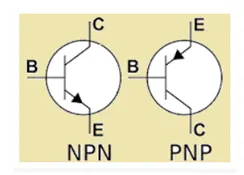
BJT Symbol
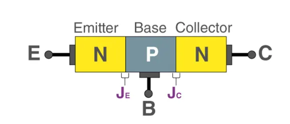
Construction of Bipolar Junction Transistor :
BJT is a semiconductor device that is constructed with 3 doped semiconductor Regions i.e. Base, Collector & Emitter separated by 2 p-n Junctions.
Bipolar transistors are manufactured in two types, PNP and NPN, and are available as separate components, usually in large quantities. The prime use or function of this type of transistor is to amplify current. This makes them useful as switches or amplifiers. They have a wide application in electronic devices like mobile phones, televisions, radio transmitters, and industrial control.
Operation of Bipolar Junction Transistor
There are three operating regions of a bipolar junction transistor:
1 Active region: The region in which the transistors operate as an amplifier.
2 Saturation region: The region in which the transistor is fully on and operates as a switch such that collector current is equal to the saturation current.
3 Cut-off region: The region in which the transistor is fully off and collector current is equal to zero.
Types of Bipolar Junction Transistor
There are two types of bipolar junction transistors:
1 PNP bipolar junction transistor
2 NPN bipolar junction transistor
PNP BJT
In PNP BJT, the n-type semiconductor is sandwiched between the two p-type semiconductors. The two p-type semiconductors act as emitter and collector respectively while the n-type semiconductor acts as a base. This is shown in the figure below.
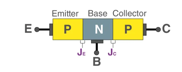
The current enters the transistor through the emitter such that the emitter-base junction is forward biased and the collector-base junction is reverse biased.
NPN BJT
In NPN BJT, p-type semiconductor is sandwiched between the two n-type semiconductors. The two n-type semiconductors act as emitter and collector respectively while the p-type semiconductor acts as a base. This is shown in the figure below.
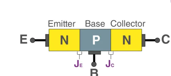
Current entering the emitter, base, and collector has the sign convention of positive while the current that leaves the transistor has the sign convention of negative.
Function of Bipolar Junction Transistor
BJTs are of two types namely NPN and PNP based on doping types of the three main terminals. An NPN transistor consists of two semiconductor junctions that have a thin p-doped anode region and PNP transistor also consists of two semiconductors junctions that have a thin n- doped cathode region.
The flow of charge in a Bipolar transistor is due to the diffusion of charge carriers between the two regions belonging to different charge concentrations. Regions of BJT are known as the base, collector, and emitter.
The emitter region is highly doped when compared to other layers. Both collector and base layers have the same charge carrier concentrations. Among these junctions, the base-emitter junction is forward biased, and the base-collector junction is reverse biased. Forward biased means p-doped region has more potential than the n-doped side.
Characteristics of different transistor configurations are given in the following table:
|
Characteristics |
Common Base |
Common Emitter |
Common Collector |
|
Power Gain |
low |
Very high |
medium |
|
Current gain |
low |
medium |
high |
|
Voltage gain |
High |
Medium |
low |
|
Phase angle |
0 |
180 |
0 |
|
Output impedance |
Very high |
high |
low |
|
Input Impedance |
Low |
medium |
high |
Applications of BJT
We know that a bipolar junction transistor is used as a switch, as an amplifier, as a filter, and even as an oscillator. Below is the list of other applications of bipolar junction transistor:
BJT is used as a detector or also known as a demodulator.
BJT finds application in clipping circuits so that the waves can be shaped.
Logic circuits and switching circuits use BJT.
Dc Motor:
A DC motor is an electrical machine that converts electrical energy into mechanical energy. In a DC motor, the input electrical energy is the direct current which is transformed into the mechanical rotation.
Definition of DC motor
A DC motor is defined as a class of electrical motors that convert direct current electrical energy into mechanical energy.
From the above definition, we can conclude that any electric motor that is operated using direct current or DC is called a DC motor.
DC Motor Diagram:
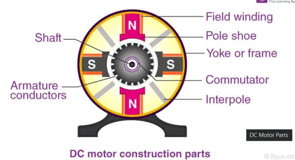
Different Parts of a DC motor
A DC motor is composed of the following main parts::
Armature or Rotor
The armature of a DC motor is a cylinder of magnetic laminations that are insulated from one another. The armature is perpendicular to the axis of the cylinder. The armature is a rotating part that rotates on its axis and is separated from the field coil by an air gap.
Field Coil or Stator
A DC motor field coil is a non-moving part on which winding is wound to produce a magnetic field. This electro-magnet has a cylindrical cavity between its poles.
Commutator and Brushes
Commutator
The commutator of a DC motor is a cylindrical structure that is made of copper segments stacked together but insulated from each other using mica. The primary function of a commutator is to supply electrical current to the armature winding.
Brushes
The brushes of a DC motor are made with graphite and carbon structure. These brushes conduct electric current from the external circuit to the rotating commutator. Hence, we come to understand that the commutator and the brush unit are concerned with transmitting the power from the static electrical circuit to the mechanically rotating region or the rotor.
DC Motor Working Explained
In the previous section, we discussed the various components of a DC motor. Now, using this knowledge let us understand the working of DC motors.
A magnetic field arises in the air gap when the field coil of the DC motor is energized. The created magnetic field is in the direction of the radii of the armature. The magnetic field enters the armature from the North pole side of the field coil and “exits” the armature from the field coil’s South pole side.
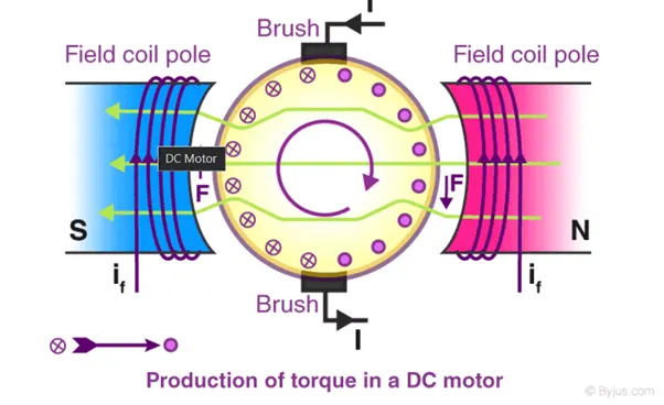
The conductors located on the other pole are subjected to a force of the same intensity but in the opposite direction. These two opposing forces create a torque that causes the motor armature to rotate.
Working principle of DC motor
When kept in a magnetic field, a current-carrying conductor gains torque and develops a tendency to move. In short, when electric fields and magnetic fields interact, a mechanical force arises. This is the principle on which the DC motors work.
Diode
A diode is a two-terminal electronic component that conducts electricity primarily in one direction. It has high resistance on one end and low resistance on the other end. In this article, let us understand in detail about what is diode.
Diodes are used to protect circuits by limiting the voltage and to also transform AC into DC. Semiconductors like silicon and germanium are used to make the most of the diodes. Even though they transmit current in a single direction, the way with which they transmit differs. There are different kinds of diodes and each type has its own applications.
Diode Symbol :
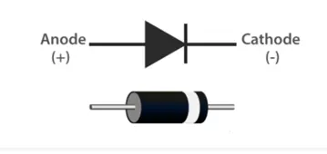
A standard diode symbol is represented as above. In the above diagram, we can see that there two terminals that are known as anode and cathode. The arrowhead is the anode that represents the direction of the conventional current flow in the forward biased condition. The other end is the cathode.
Diode Construction
Diodes can be made of either of the two semiconductor materials, silicon and germanium. When the anode voltage is more positive than the cathode voltage, the diode is said to be forward-biased, and it conducts readily with a
relatively low-voltage drop. Likewise, when the cathode voltage is more positive than the anode, the diode is said to be reverse-biased. The arrow in the diode symbol represents the direction of conventional current flow when the diode conducts.
Characteristics Of Diode
The following are the characteristics of the diode:
Forward-biased diode
Reverse-biased diode
Zero biased diode
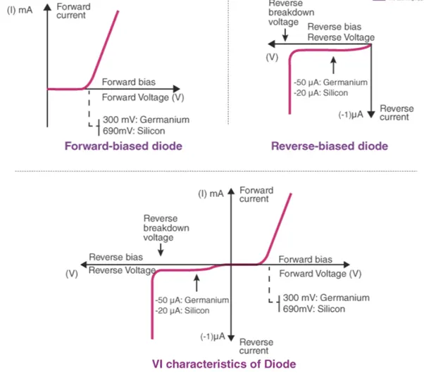
Forward-biased Diode
There is a small drop of voltage across the diode when the diode is forward-biased and the current is conducting. For silicon diodes, the forward voltage is 690mV and for germanium, 300mV is the forward voltage. The potential energy across the p-type material is positive and across the n-type material, the potential energy is negative.
Reverse-biased Diode
A diode is said to be reverse-biased when the battery’s voltage is dropped completely. For silicon diodes, the reverse voltage is -20μA and for germanium, -50μA is the reverse voltage. The potential energy across the p-type material is negative and across the n-type material, the potential energy is positive.
Zero-biased Diode
When the diode is zero-biased, the voltage potential across the diode is zero.
Diode Applications
Following are the applications and uses of the diode:
Diodes as a rectifier
Diodes in the clipping circuit
Diodes in clamping circuits
Diodes in logical gates
Diodes in reverse current protection
H Bridge Circuit:
An H-bridge is a simple circuit that lets you control a DC motor to go backward or forward.
H-Bridge concept
Here’s the concept of the H-bridge:
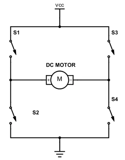
A DC motor spins either backward or forward, depending on how you connect the plus and the minus.
If you close switch 1 and 4, you have plus connected to the left side of the motor and minus to the other side. And the motor will start spinning in one direction.
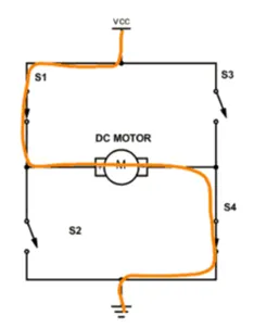
If you instead close switch 2 and 3, you have plus connected to the right side and minus to the left side. And the motor spins in the opposite direction.
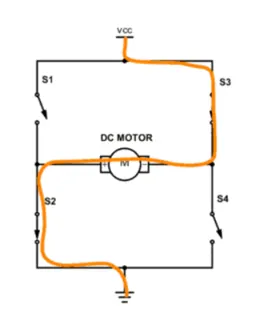
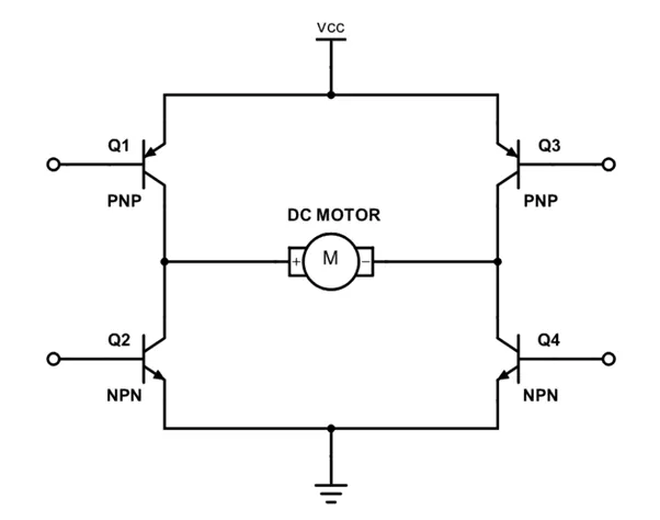
Since the transistor can be a switch, you’ll be able to make the motor spin in either direction by turning on and off the four transistors in the circuit above.
Now we try to understand the model.
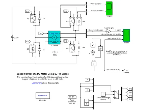
The DC motor model have configuration of 5 HP 240 V 1750 rpm. The Bipolar Junction Transistor (BJT) used for power switching applications and operates as an IGBT. When it is conducting (BJT operating in the saturated region), a forward voltage V, is developed between collector and emitter (in the range of 1 V). Therefore, the IGBT block can be used to model the BJT device.
The H-bridge consists of four BJT and four Diode pairs (BJT simulated by IGBT models). Any two transistors are switched simultaneously: Q1 and Q4 or Q2 and Q3. When Q1 and Q4 are fired, a positive voltage is applied to the motor and diodes D2-D3 operate as free wheeling diodes when Q1 and Q4 are switched off. When Q2 and Q3 are fired, a negative voltage is applied to the motor and diodes D1-D4 operate as free-wheeling diodes when Q2 and Q3 are switched off.
At below of the model there is block of switches namely p1, p2, p3, p4. The switch is controlled by a signal (1/0). It simulates a fan type load (where Load torque is proportional to square of speed).These inputs are in Goto from block.
That block is used to send signal to "From Block" that have the specified tag
These 4 types of Input are connected to transistor Q1, Q2, Q3, and Q4 through "From Block"; An "From block" Receives the Signal from the "Goto Block" with the specified tag. The block icon displays the selected tag name.
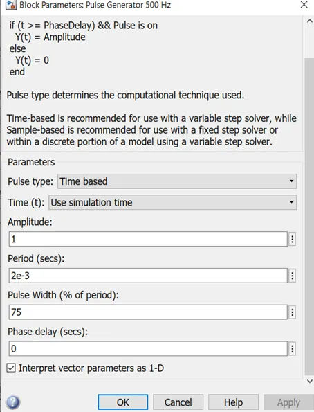
The Pulse Generator is used to generate pulses which are fed to the four IGBTs to create Pulse Width Modulation. The motor starts in the positive direction with a duty cycle of 75% .
Result
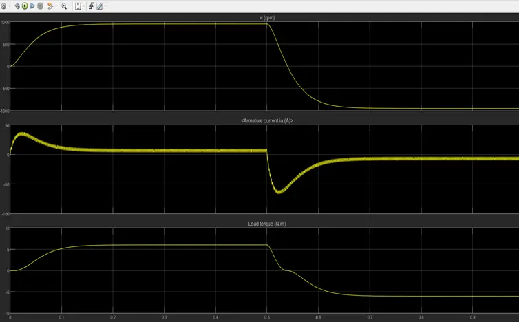
At t = 0.5 sec., the armature current is reversed and the motor runs in the negative direction. So in the first half cycle, we can see the motor attains a speed of 1000 rpm a load torque of 6 N.m whereas in the second half cycle the same situation occur but in the negative direction. Here we can see that the armature current of DC motor get shoot up.
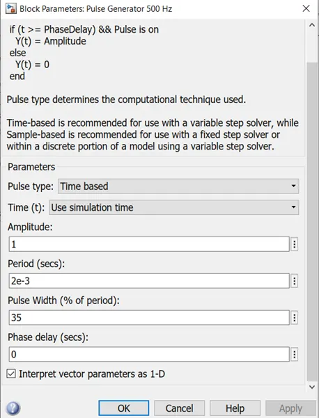
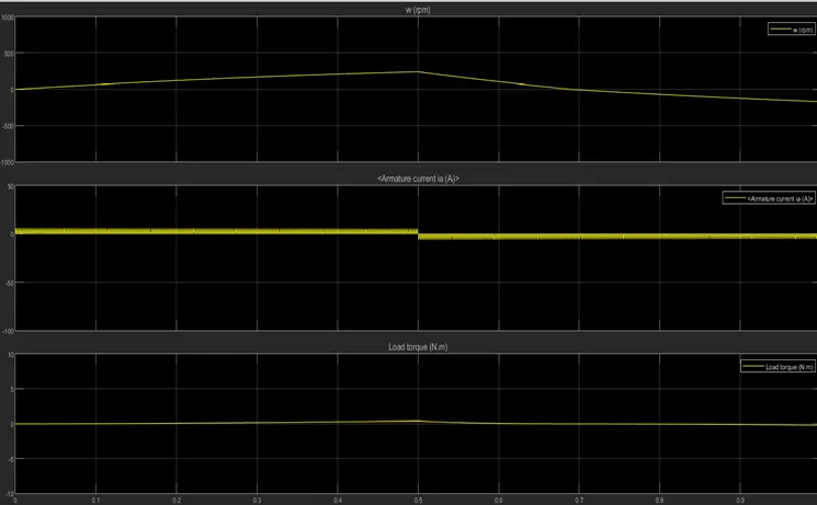
Here we can observe that the Armature current is almost 0 A, that means the armature current doesn't shoot up at 35% pulse width. Also the motor speed and torque is reduced to 250 rpm and 0.5 N.m respectively due to the reduction in Pulse width. This indicates that, as we reduce the pulse width, the motor speed and torque reduces . And to avoid armature shoot up, we will have to reduce the pulse width from the pulse generator.
c) Refer to the help section of ‘The Four-Quadrant Chopper DC Drive (DC7) block’. Compare it with the H-bridge model.
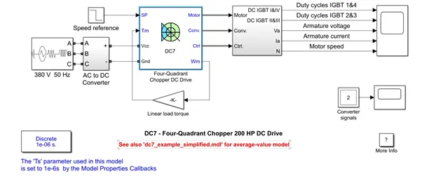
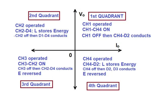
A four quadrant chopper is a chopper which can operated in all the four quadrants. The power can flow either from source to load or load to source in this chopper. In first quadrant, a Class-E chopper acts as a Step-down chopper whereas in second quadrant it behaves as a Step-up chopper. This type of chopper is also known as Class-E or Type-E chopper.
Working Principle / Operation of Class-E Chopper:
The circuit of a four quadrant chopper or class-E chopper basically consists of four semiconductor switches CH1 to CH4 and four diodes D1 to D4. The four diodes are connected in anti-parallel. The circuit diagram of this type of chopper is shown below.
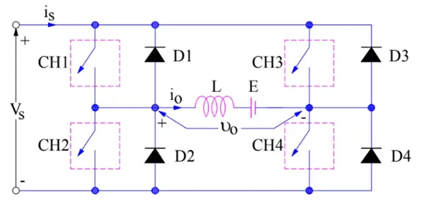
In the above circuit diagram, the choppers are numbered CH1 to CH4. For first quadrant operation CH1 is made ON, for second quadrant operation CH2 is made ON and so on.
The operation of the four Quadrant chopper is given below:
The converter is fed by a 515 V DC bus obtained by rectification of a 380 V AC 50 Hz voltage source. In order to limit the DC bus voltage during dynamic braking mode, a braking chopper has been added between the diode rectifier and the DC7 block. The 200 HP DC motor is separately excited with a constant 150 V DC field voltage source. The armature voltage is provided by an IGBT converter controlled by two Pl regulators .
The current regulatory controls the armature current by computing the appropriate duty ratios of the 5 kHz pulses of the four IGBT devices (Pulse Width Modulation).
So now we see the difference between The Four-Quadrant Chopper DC Drive (DC7) block and the H bridge model
In four Quadrant Chopper DC drive there are four quadrants like Forward Motoring, Regenerative Braking,Reverse Motoring and Reverse Regenerative Braking. Whereas in H-bridge supplies an irregular current for each sector that causes voltage Fluctuation in armature current and it consist of 2 Operation namely they are Forward Motoring. Reverse Motoring.
The efficiency is high in Chopper compare with H-bridge and Maintenance is less than H-bridge.
In H-bridge we need to change Polarity which turns into opposite direction to control the motor whereas in chopper model we need to interrupt one signal under control of another.
Bjt H Drive is used for changing the direction of the Motor for forward and reverse. In four quadrant chopper drive the Motor can be Operated in four different Mode (Forward Motoring and Braking, Reverse Motoring and Braking).
In Bjt H Drive the Regenerative Braking isn’t available. In four quadrant chopper drive the Regenerative Braking can be Achieved.
In Bjt H Drive the source is of Fixed DC supply but in four quadrant chopper drive the source is an of AC supply which can be rectified to DC varying supply.
In Bjt H Drive signals are continuous and in four quadrant chopper drive Signals are not continuous and they are discrete.
In Bjt H drive there is less control of the Vehicle and in four quadrant chopper drive there is better control of the Vehicle.
Ref - https://www.tutorialspoint.com/power_electronics/power_electronics_bjt.htm
2) Develop a 2-quadrant chopper using Simulink & explain the working of the same with the relevant results.
Two Quadrant Chopper is also known as Type C Chopper
This is a two-quadrant chopper whose operation is bounded between first and second quadrant of Vo – Io plane. This type of chopper obtained by connecting type-A and type-B chopper in parallel as shown in the figure.
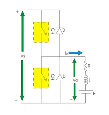
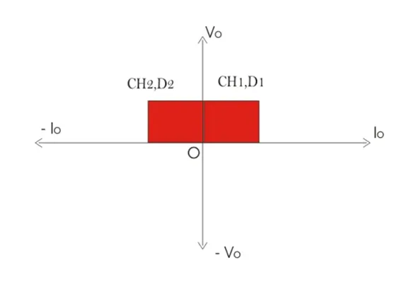
When CH1 is ON current flows through abcdefa and inductor L will be charged. Hence output voltage Vo and current Io both will be positive. When CH1 is OFF, induction will discharge through D1 and current Io will flow through same direction with zero output voltage. So, we can see the operation of CH1 is nothing but the operation of type-A chopper by which we can operate a chopper in the first quadrant.
When CH2 is ON, output voltage Vo will be zero but output current Io will flow in opposite direction of current shown in the figure and inductor will be charged up. When CH2 is OFF.
Output voltage.
Vo = [ E + Ldi/dt – IR ]
Which exceeds the value of source voltage VS. So current flows through diode D2 and treated as negative. Hence output voltage Vo is always positive and output current Io is always negative here. We can see operation of CH2 is nothing but operation of type-B chopper by which we can operate the chopper in the second quadrant.
We can conclude that the operation of type-C chopper is the combined operation of type-A and type-B chopper. This type of chopper is suitable for both forward motoring and forward braking operation.
Now we understand the model : -
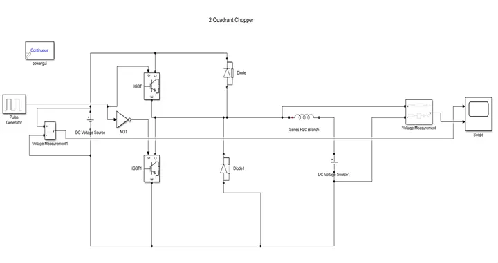
Blocks that we used :
DC Voltage source: It is the source voltage of 100V.
IGBT: Insulate gate bipolar transistor is used as a chopper.
Pulse generator: This block is used to control the gate of IGBT.
Diode: It is a P-N junction diode
Inductor
Voltage measurement: To measure the voltage.
PowerGUI
Source voltage of 100V is used and its positive terminal is connected to collector of IGBT block.
To operate CH-1, duty cycle of 50% is used. Maximum amplitude of 1 is used. For CH-2 just a phase delay of 0.5 sec is given.
Then connect the diodes in parallel to the choppers as shown in figure and connect the inductor . Voltage measurement block is used to measure the voltage at input and outputand plot all these things using scope. And add gui block.
Result
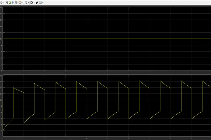
From result we can conclude that the operation of 2 Quadrant chopper is the combined operation of type-A and type-B chopper. This type of chopper is suitable for both forward motoring and forward braking operation. And we can vary the fixed voltage to variable voltage.
3) Explain in a brief about operation of BLDC motor.
A brushless DC motor (also known as a BLDC motor or BL motor) is an electronically commuted DC motor which does not have brushes. The controller provides pulses of current to the motor windings which control the speed and torque of the synchronous motor.
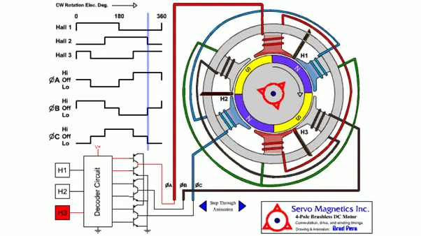
These types of motors are highly efficient in producing a large amount of torque over a vast speed range. In brushless motors, permanent magnets rotate around a fixed armature and overcome the problem of connecting current to the armature. Commutation with electronics has a large scope of capabilities and flexibility. They are known for smooth operation and holding torque when stationary.
In brushes motors, there are permanent magnets on the outside and a spinning armature which contains electromagnet is inside. These electromagnets create a magnetic field in the armature when the power is switched on and help to rotate the armature.
The brushes change the polarity of the pole to keep the rotation on of the armature. The basic working principle for the brushed DC motor and for brushless DC motor are same i.e. internal shaft position feedback.
Brushless DC motor has only two basic parts: rotor and the stator. The rotor is the rotating part and has rotor magnets whereas stator is the stationary part and contains stator windings. In BLDC permanent magnets are attached in the rotor and move the electromagnets to the stator. The high-power transistors are used to activate electromagnets for the shaft turns. The controller performs power distribution by using a solid-state circuit.
Types of Brushless DC Motors
Basically, BLDC are of two types, one is outer rotor motor and other is inner rotor motor. The basic difference between the two is only in designing, their working principles are same.
Inner Rotor Design
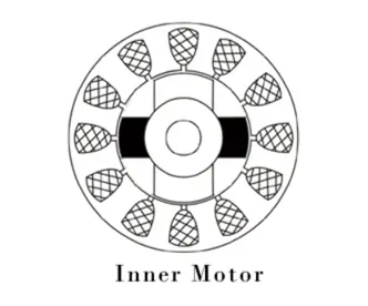
In an inner rotor design, the rotor is located in the centre of the motor and the stator winding surround the rotor. As the rotor is located in the core, rotor magnets do not insulate heat inside and heat get dissipated easily. Due to this reason, inner rotor designed motor produces a large amount of torque and validly used.
Outer Rotor Design
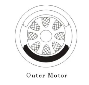
In outer rotor design, the rotor surrounds the winding which is located in the core of the motor. The magnets in the rotor trap the heat of the motor inside and do not allow to dissipate from the motor. Such type of designed motor operates at lower rated current and has low cogging torque.
Advantages of Brushless DC Motor
Brushless motors are more efficient as its velocity is determined by the frequency at which current is supplied, not the voltage.
As brushes are absent, the mechanical energy loss due to friction is less which enhanced efficiency.
BLDC motor can operate at high-speed under any condition.
There is no sparking and much less noise during operation.
More electromagnets could be used on the stator for more precise control.
BLDC motors accelerate and decelerate easily as they are having low rotor inertia.
It is high performance motor that provides large torque per cubic inch over a vast sped rang.
BLDC motors do not have brushes which make it more reliable, high life expectancies, and maintenance free operation.
There is no ionizing sparks from the commutator, and electromagnetic interference is also get reduced.
Such motors cooled by conduction and no air flow are required for inside cooling.
Disadvantages of Brushless DC Motors
BLDC motor cost more than a brushed DC motor.
The limited high power could be supplied to BLDC motor, otherwise, too much heat weakens the magnets and the insulation of winding may get damaged.