Week-7 Challenge: DC Motor Control
1)A. Explain a MATLAB demo model named ‘Speed control of a DC motor using BJT H-bridge’.
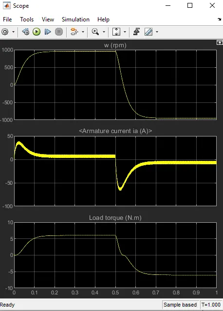
Comment on the armature current shoot-up from the scope results.
Speed control of Dc motor using bjt h bridge-
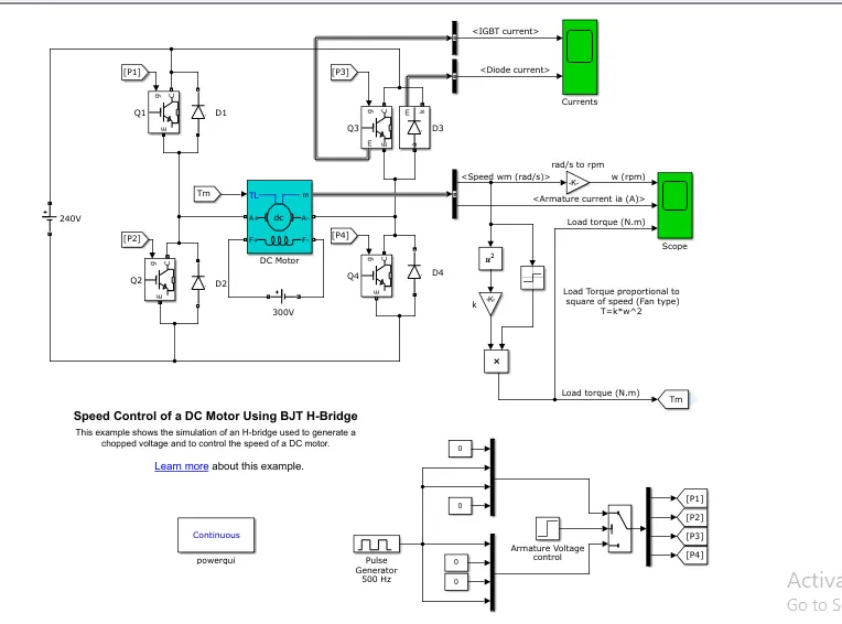
Defining the above model-
The Bipolar Junction Transistor (BJT) when used for power switching applications, operates as an IGBT. When it is conducting (BJT operating in the saturated region), a forward voltage Vf is developed between collector and emitter (in the range of 1 V). Therefore, the IGBT block can be used to model the BJT device.
The IGBT block does not simulate the gate current controlling the BJT or IGBT. The switch is controlled by a Simulink® signal (1/0). The DC motor uses the preset model (5 HP 24V 1750 rpm). It simulates a fan type load (where Load torque is proportional to square of speed). The armature mean voltage can be varied from 0 to 240 V when the duty cycle (specified in the Pulse Generator block) is varied from 0 to 100%.
The H-bridge consists of four BJT/Diode pairs (BJT simulated by IGBT models). Two transistors are switched simultaneously: Q1 and Q4 or Q2 and Q3. When Q1 and Q4 are fired, a positive voltage is applied to the motor and diodes D2-D3 operate as free-wheeling diodes when Q1 and Q4 are switched off. When Q2 and Q3 are fired, a negative voltage is applied to the motor and diodes D1-D4 operate as free-wheeling diodes when Q2 and Q3 are switched off.
result of Armature current shoot up-
change in pulse width, to see how armature shoot current is changing-
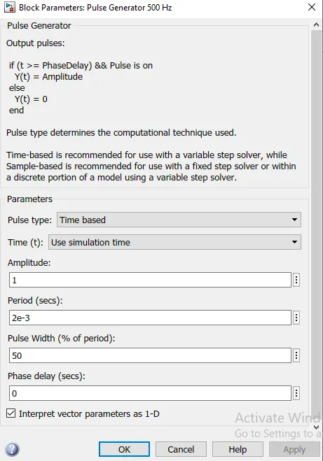
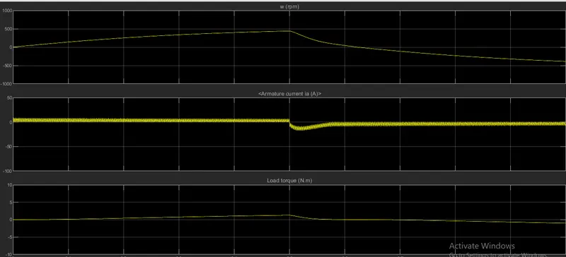
There has been decrease in shoot current if pulse width is changed, so it can be concluded that with decrease in pulse width armature shoot current can be decreased.
2)Refer to the help section of ‘The Four-Quadrant Chopper DC Drive (DC7) block’. Compare it with the H-bridge model.
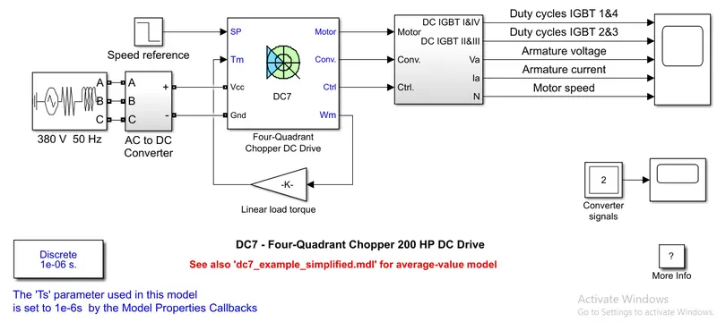
The 200 HP DC motor is separately excited with a constant 150 V DC field voltage source. The armature voltage is provided by an IGBT converter controlled by two PI regulators. The converter is fed by a 515 V DC bus obtained by rectification of a 380 V AC 50 Hz voltage source. In order to limit the DC bus voltage during dynamic braking mode, a braking chopper has been added between the diode rectifier and the DC7 block.
The first regulator is a speed regulator, followed by a current regulator. The speed regulator outputs the armature current reference (in p.u.) used by the current controller in order to obtain the electromagnetic torque needed to reach the desired speed. The speed reference change rate follows acceleration and deceleration ramps in order to avoid sudden reference changes that could cause armature over-current and destabilize the system. The current regulator controls the armature current by computing the appropriate duty ratios of the 5 kHz pulses of the four IGBT devices (Pulse Width Modulation). For proper system behaviour, the instantaneous pulse values of IGBT devices 1 and 4 are opposite to those of IGBT devices 2 and 3. This generates the average armature voltage needed to obtain the desired armature current. In order to limit the amplitude of the current oscillations, a smoothing inductance is placed in series with the armature circuit.
Comparison between h bridge and four quadrant chopper circuit
Comparison between Class E chopper and H-bridge-
|
S.No. |
Class E Chopper |
H-Bridge |
|
1 |
Regenerative braking is possible |
regenerative braking is not possible |
|
2 |
In this four modes of operation is possible(forward,reverse,forward braking and reverse braking) |
Only forward and reverse are possible. |
|
3 |
Two PI regulator are used. (speed regulator and current regulator) |
PI regulator are not used |
|
4 |
Four-quadrant Chopper is electronic switch that is used to interupt one signal under the control of another. |
H-bridge is a electronic circuit that switches the polarity of voltage applied to the load. |
|
5 |
this has numerous advantage and majorly employed in automobile | This are majorly used in robots. |
|
6 |
this has better efficency |
This has cpmpartively less efficency |
|
7 |
Maintanence required is less |
Risk of damage due to current spike. |
2)Develop a 2-quadrant chopper using simulink & explain the working of the same with the relevant results.
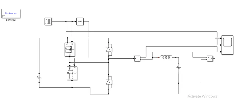
Blocks required for two quadrant chopper-
- Mosfet
- diode
- rlc block
- voltage and current sensor
- pulse generator
- battery source
- Not gate
- scope
- Arrange the blocks as per the reqirment of the condition
- click on mosfet and diode and disable the measurment
- open the rlc block and keep as inductance default.
- Not gate is used so that both switches don't work together.
- Open the pulse generator and decide the condition for which the current should flow to which mosfet and inductance which will be decided by not gate.
results obtained-
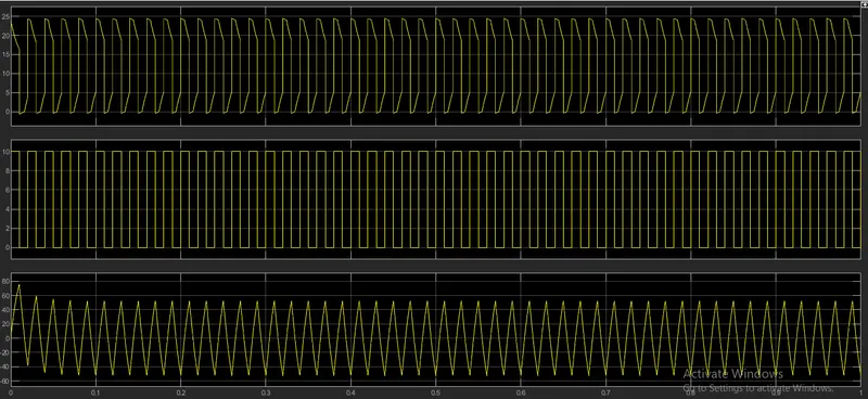
in first graph that is indicating the voltage and in the second graph there has been generated pulse voltage and it can be varied according to us and in third graph there has been graph of current whose value are both positive and negative.
BLDC motor-
Brushed dc motor problem-
The commutator has disadvantages that has led to a decline in use of brushed motors. These disadvantages are:
- The friction of the brushes sliding along the rotating commutator segments causes power losses that can be significant in a low power motor.
- The soft brush material wears down due to friction, creating dust, and eventually the brushes must be replaced. This makes commutated motors unsuitable for low particulate or sealed applications like hard disk motors, and for applications that require maintenance-free operation.
- The electrical resistance of the sliding brush contact causes a voltage drop in the motor circuit called brush drop which consumes energy.
- The repeated abrupt switching of the current through the inductance of the windings causes sparks at the commutator contacts, which is a fire hazard in explosive atmospheres and a source of electronic noise, which can cause electromagnetic interfrence, in nearby microelectronic circuits.
Solution by brushless dc motor-
Brushless motors offer several advantages over brushed DC motors, including high torque to weight ratio, increased efficiency producing more torque per watt, increased reliability, reduced noise, longer lifetime by eliminating brush and commutator erosion, elimination of ionizing sparks from the commutator, and an overall reduction of electromagnetic interfrence (EMI). With no windings on the rotor, they are not subjected to centrifugal forces, and because the windings are supported by the housing, they can be cooled by conduction, requiring no airflow inside the motor for cooling. This in turn means that the motor's internals can be entirely enclosed and protected from dirt or other foreign matter.
Construction of bldc motor-
In this motor, the permanent magnets attach to the rotor. The current-carrying conductors or armature winding are located on the stator. They use electrical commutation to convert electrical energy into mechanical energy.
The main design difference between a brushed and brushless motors is the replacement of mechanical commutator with an electric switch circuit. A BLDC Motor is a type of synchronous motor in the sense that the magnetic field generated by the stator and the rotor revolve at the same frequency.
Brushless motor does not have any current carrying commutator. The field inside a brushless motor is switched through an amplifier which is triggered by the commutating device like an optical encoder.
Working of bldc motor-
BLDC motor works on the principle similar to that of a Brushed Dc motor. The Lorentz force law which states that whenever a current carrying conductor placed in a magnetic field it experiences a force. As a consequence of reaction force, the magnet will experience an equal and opposite force. In the BLDC motor, the current carrying conductor is stationary and the permanent magnet is moving.
And the permanent magnet keeps moving as it'll try to keep approaching the next pole and the magnet which is generated behind it'll try to oppose it so that enough torque is created.
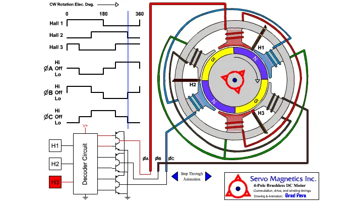
And how do we know where should be current passed so that permanenet magnet starts working it's done by hall sensor which help us out to where should be the current passed.
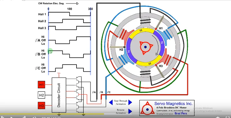
In the above image it's trying to explain that when hall sesnor1 and hall sensor 3 detect south pole they get activated and because of this current flows through the b phase which is high and then the current is outgoing through blue wire and this helps to create different magnetic field with respect to time.
And this keeps continuing as whichever hall sesnor detects the south pole there is current flow through different phase and which it helps the stator which is permanenet magnet to flow and produce torque.
And this keeps continuing with time.
A small gif which shows how this keeps continuation-