Week-7 Challenge: DC Motor Control
SIMULINK MODEL: DC MOTOR CONTROL
AIM:
- A. Explain a MATLAB demo model named ‘Speed control of a DC motor using BJT H-bridge’.
- Comment on the armature current shoot-up from the scope results.
- Refer to the help section of ‘The Four-Quadrant Chopper DC Drive (DC7) block’. Compare it with the H-bridge model.
- Develop a 2-quadrant chopper using simulink & explain the working of the same with the relevant results. (Refer to article – Multi quadrant operation of motor)
- Explain in a brief about operation of BLDC motor.
SOLUTION:
- A)
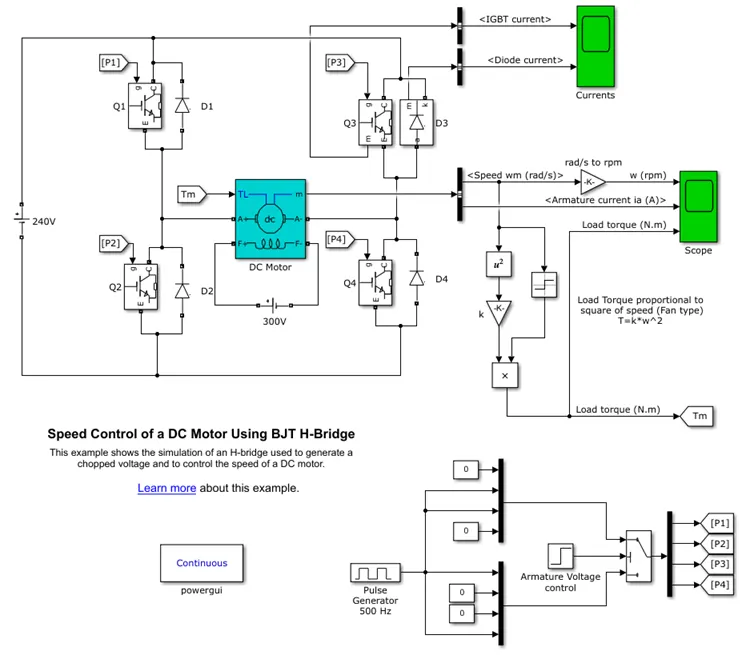
The Bipolar Junction Transistor (BJT) when used for power switching applications, operates as an IGBT. When it is conducting (BJT operating in the saturated region), a forward voltage Vf is developed between collector and emitter (in the range of 1 V). Therefore, the IGBT block can be used to model the BJT device.
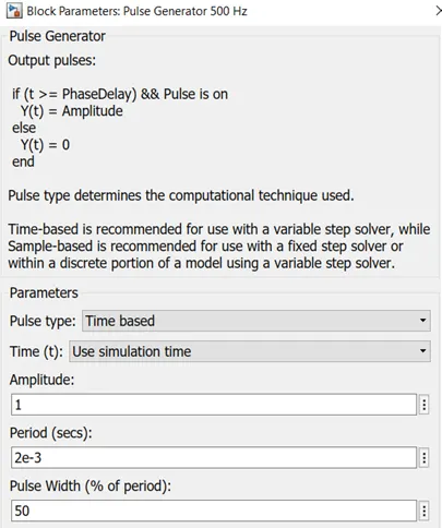
The IGBT block does not simulate the gate current controlling the BJT or IGBT. The switch is controlled by a Simulink® signal (1/0). The DC motor uses the preset model (5 HP 24V 1750 rpm). It simulates a fan type load (where Load torque is proportional to square of speed). The armature mean voltage can be varied from 0 to 240 V when the duty cycle (specified in the Pulse Generator block) is varied from 0 to 100%.
The H-bridge consists of four BJT/Diode pairs (BJT simulated by IGBT models). Two transistors are switched simultaneously: Q1 and Q4 or Q2 and Q3. When Q1 and Q4 are fired, a positive voltage is applied to the motor and diodes D2-D3 operate as free-wheeling diodes when Q1 and Q4 are switched off. When Q2 and Q3 are fired, a negative voltage is applied to the motor and diodes D1-D4 operate as free-wheeling diodes when Q2 and Q3 are switched off.
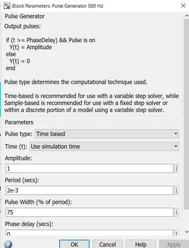
When the pulse width is 75, the following output is obtained.
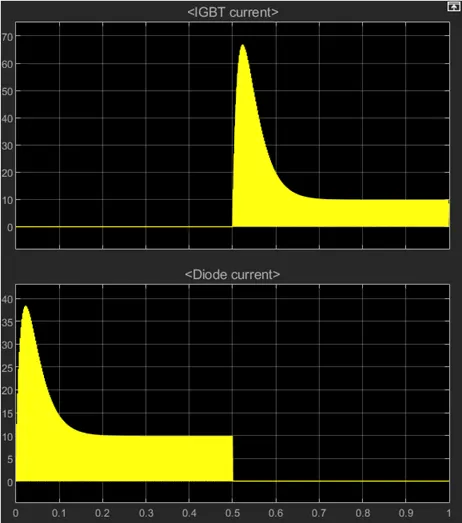
The IGBT current is given for a duration of 0 to 1 sec and the diode current is given for a duration of 0 to 0.5 sec.
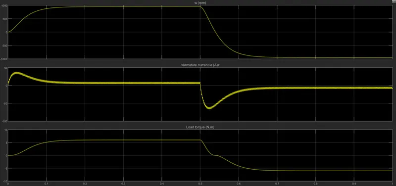
During this period, the armature current shows a slight transient.
For a duty cycle of 50%, the following output is obtained.
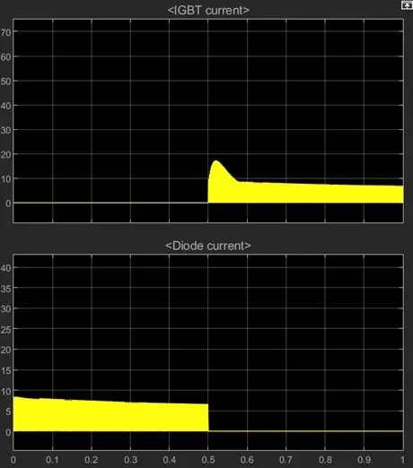
As the duty cycle decreases, the diode current falls below 10A and the motor speed also decreases to less than 500 rpm.
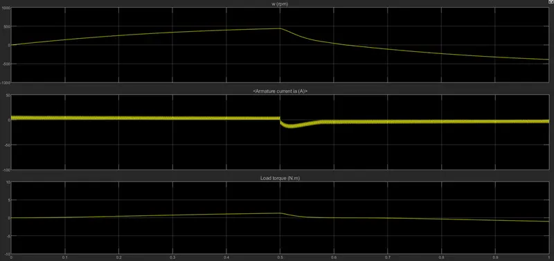
So as the duty cycle reduces, the motor speed also reduces. In order to achieve higher rpm, the duty cycle should also be high.
B)
The sudden peaks can be reduced by reducing the duty cycle. In the above case, we reduced the duty cycle to 50%. Now we will reduce it to 30% and observe the results.
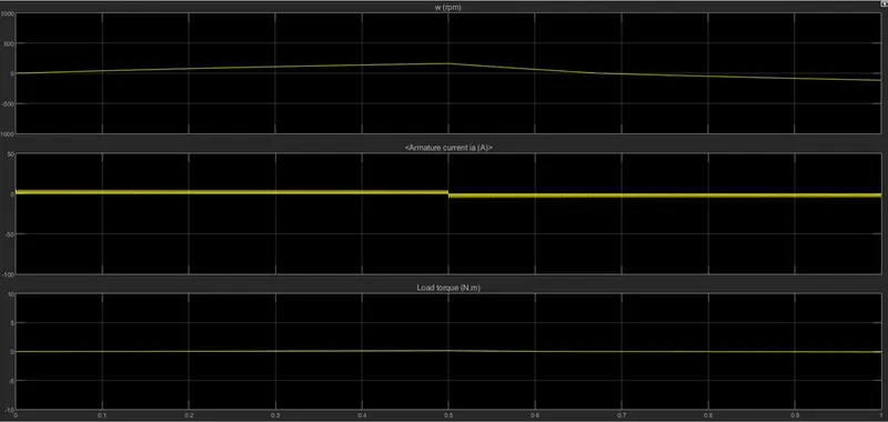
We can observe that the sudden change in the output is completely reduced. Hence it is proved that as the duty cycle reduces, the sudden peak in the output is also minimised.
C)
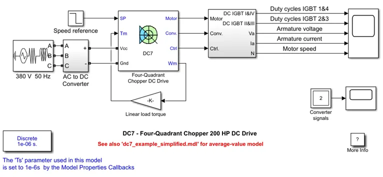
The 200 HP DC motor is separately excited with a constant 150 V DC field voltage source. The armature voltage is provided by an IGBT converter controlled by two PI regulators. The converter is fed by a 515 V DC bus obtained by rectification of a 380 V AC 50 Hz voltage source. In order to limit the DC bus voltage during dynamic braking mode, a braking chopper has been added between the diode rectifier and the DC7 block.
The first regulator is a speed regulator, followed by a current regulator. The speed regulator outputs the armature current reference (in p.u.) used by the current controller in order to obtain the electromagnetic torque needed to reach the desired speed. The speed reference change rate follows acceleration and deceleration ramps in order to avoid sudden reference changes that could cause armature over-current and destabilize the system. The current regulator controls the armature current by computing the appropriate duty ratios of the 5 kHz pulses of the four IGBT devices (Pulse Width Modulation). For proper system behaviour, the instantaneous pulse values of IGBT devices 1 and 4 are opposite to those of IGBT devices 2 and 3. This generates the average armature voltage needed to obtain the desired armature current. In order to limit the amplitude of the current oscillations, a smoothing inductance is placed in series with the armature circuit.
- Before starting the simulation, set the initial bus voltage to 515 V via the GUI block ('Initial States Setting' button and 'Cbus' variable).
- Start the simulation. You can observe the motor armature voltage and current, the four IGBT pulses and the motor speed on the scope. The current and speed references are also shown.
- The motor is coupled to a linear load, which means that the mechanical torque of the load is proportional to the speed.
- The speed reference is set at 500 rpm at t = 0 s. Observe that the motor speed follows the reference ramp accurately (+400 rpm/s) and reaches steady state around t = 1.3 s.
- The armature current follows the current reference very well, with fast response time and small ripples. Notice that the current ripple frequency is 5 kHz.
- At t = 2 s, speed reference drops to -1184 rpm. The current reference decreases to reduce the electromagnetic torque and causes the motor to decelerate with the help of the load torque.
- At t = 2.2 s, the current reverses in order to produce a braking electromagnetic torque (dynamic braking mode). This causes the DC bus voltage to increase.
- At t = 3.25 s, the motor reaches 0 rpm and the load torque reverses and becomes negative. The negative current now produces an accelerating electromagnetic torque to allow the motor to follow the negative speed ramp (-400 rpm/s). At t = 6.3 s, the speed reaches -1184 rpm and stabilizes around its reference.
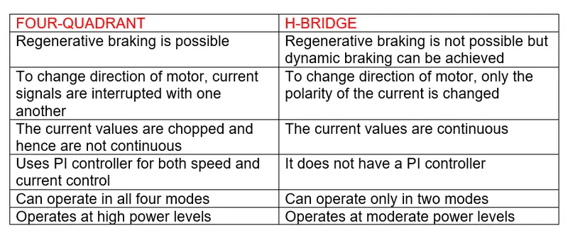
Comparison of Four-Quadrant Chopper DC Drive with H bridge model
2.
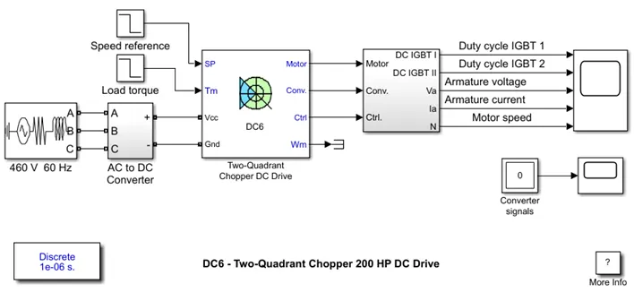
The 200 HP DC motor is separately excited with a constant 150 V DC field voltage source. The armature voltage is provided by an IGBT buck-boost converter controlled by two PI regulators. The buck-boost converter is fed by a 630 V DC bus obtained by rectification of a 460 V AC 60 Hz voltage source. In order to limit the DC bus voltage during dynamic braking mode, a braking chopper has been added between the diode rectifier and the DC6 block.The first regulator is a speed regulator, followed by a current regulator. The speed regulator outputs the armature current reference (in p.u.) used by the current controller in order to obtain the electromagnetic torque needed to reach the desired speed. The speed reference change rate follows acceleration and deceleration ramps in order to avoid sudden reference changes that could cause armature over-current and destabilize the system. The current regulator controls the armature current by computing the appropriate duty ratios of the 5 kHz pulses of the two IGBT devices (Pulse Width Modulation).For proper system behaviour, the two IGBT devices have opposite instantaneous pulse values. This generates the average armature voltage needed to obtain the desired armature current. In order to limit the amplitude of the current oscillations, a smoothing inductance is placed in series with the armature circuit.
- Before starting the simulation, set the initial bus voltage to 630 V via the GUI block ('Initial States Setting' button and 'Cbus' variable).
- Start the simulation. You can observe the motor armature voltage and current, the two IGBT pulses and the motor speed on the scope. The current and speed references are also shown.
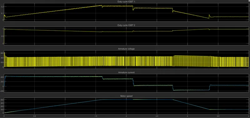
- The speed reference is set at 400 rpm at t = 0 s. Initial load torque is 814 N.m.
- Observe that the motor speed follows the reference ramp accurately (+250 rpm/s) and reaches steady state around t = 2 s. The armature current follows the current reference very well, with fast response time and small ripples. Notice that the current ripple frequency is 5 kHz.
- At t = 2.1 s, the load torque passes from 814 N.m to 100 N.m. The motor speed recovers fast and is back at 400 rpm at t = 2.75 s. The current reference lowers to about 40 A to generate a smaller electromagnetic torque, the load torque being reduced. As observed before, the armature current follows its reference perfectly.
- At t = 2.75 s, the speed reference jumps down to 100 rpm. In order for the motor to decelerate following the negative speed ramp, the armature current reverses down to -160 A to generate a braking electromagnetic torque (dynamic braking mode). This causes the DC bus voltage to increase. The braking chopper limits the voltage value.
- At t = 3.4 s, the motor speed reaches 100 rpm and the current reverses back to 40 A.
- At t = 4 s, the speed stabilizes around its reference.
3.
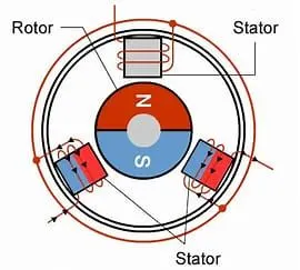
BLDC Motor also known as Brushless DC Motor is a motor-operated without brushes to overcome certain difficulties. The BLDC operates on the same law as of a regular type. This type requires some coils to be energized in order to make the rotor rotate. The coils placed in the stator slots are named as A, B, and C. When the coil A is energized by a DC supply, it gets excited and attracts the rotor permanent magnet. Similarly, when the coil B is energized rotor permanent magnet is attracted this continues when the coil C is also energized. After the coil C is energized, the coil A is again energized but with negative polarity. This continues with the remaining coils as well with negative polarity. This cycle continues alternately and the rotor continuously rotates. But there is a problem of developing the low power output. This can be overcome by connecting the free ends of two coils together I,e A and B. This produces greater power output as the coils energize double the field and pull the rotor permanent magnets along with them. This way a greater output can be achieved.The problem with the BLDC type is that which coil to energize first. It can be known by finding the position of the rotor coils. This position can be known by using a controller. The controller helps in energizing the coil after receiving the position from the sensor
Advantages
- Highly reliable
- Smoother operation
- High power output
- Can be used for higher speed applications
- No brush is required
- No sparking
- Light in weight
- Less noise
Disadvantages
- Complex operation
- Requires maintenance
- A controller is required
- Costly
- Sensors are required