Week - 4
1.CONTROL LOGIC OF WASHING MACHINE USING STATEFLOW
AIM:
To implement the control logic of a washing machine using state-flow.
CONDITIONS:
- If the power supply is available, the system gets activated
- If the Water supply is not available, stop the process & indicate through LED
- Soaking time should be 200s followed by Washing time of 100s.
- Then rinsing happens for next 20s & dryer runs for 50s
- After all the processes have completed turn on the finished LED
BLOCKS USED IN MODEL:
- Chart
- Constant
- Lamp
- Display
THEORY:
Operating a washing machine is pretty simple:
- There are a few things to decide before you start your load of clothes, such as how big the load is (small, medium, large, extra-large), what temperature the water will be for the wash and rinse cycles (cold/cold, warm/cold, warm/warm, hot/cold), how the machine should agitate (delicate, knit, permanent press, heavy), and how long the cycles should last (number of minutes, based on how soiled your clothes are).
- After you fill the tub with clothes, the machine fills the tub with water and then stirs the clothes around using an agitator.
- After sometime agitating, the washer drains the water and then spins the clothes to remove most of the water. Then, it refills, and agitates the clothes some more to rinse out the soap. Then it drains and spins again.
The drive mechanism of a washing machine has two jobs:
- To agitate the clothes, moving them back and forth inside the wash tub.
- To spin the entire wash tub, forcing the water out.
- There is a gearbox that handles these two jobs. If the motor spins in one direction, the gearbox agitates; if it spins the other way, the gearbox goes into spin cycle.
SIMULINK MODEL:
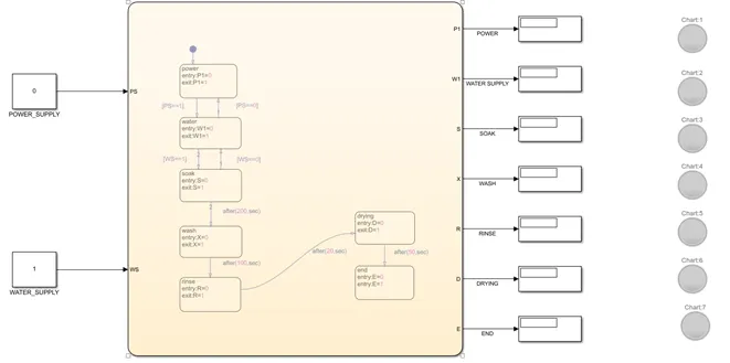
CHART:
MODEL EXPLANATION:
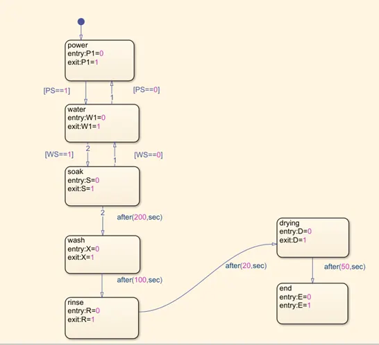
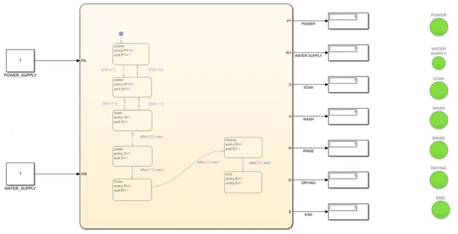
First select the chart block from the library. Double click on it to begin with the state-flow logic creation. Create seven states using the chart option from the palette available on the left side of the window. Enter the names of seven states as power, water, soak, wash, rinse, drying and end. Then we give the power supply and water supply as input. After giving the input, we give entry and exit values as 0 and 1 for all states as while entering a state, there is no ongoing process but while exiting, a process gets over and the control flows to the next state. The delay time period as given in the problem is being fed to the respective states (soaking = 200 secs, washing =100 secs, rinsing=20 secs, drying= 50 secs).
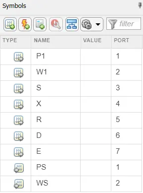
Then all the symbols that are used in the state-flow are named and categorized accordingly in the symbols pane.
At the end, we come out of the chart and give the inputs power supply and water supply as two separate constants. The output ports from the chart are connected to separate display’s and each display is connected to a separate lamp to indicate ON and OFF states.
RESULT:
When both the power supply and water supply is 1, the entire process takes place and all the LED’s go green.
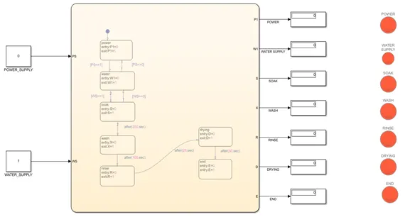
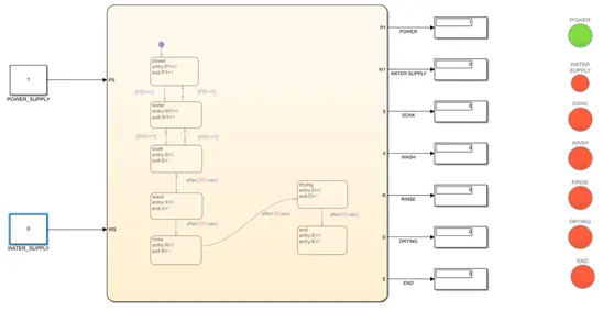
When we give 0 as input for either power supply or water supply, the full process doesn’t take place.
2.GEAR SHIFT LOGIC USING STATE FLOW
AIM:
To implement gear shift logic using state-flow
CONDITIONS:
|
Speed Range(kmph) |
Gear |
|
0 - 15 |
1 |
| 16 - 25 |
2 |
| 26 - 40 |
3 |
| 41 - 60 |
4 |
| above 61 |
5 |
BLOCKS USED IN MODEL:
- Chart
- Constant
- Slider gain
- Display
THEORY:
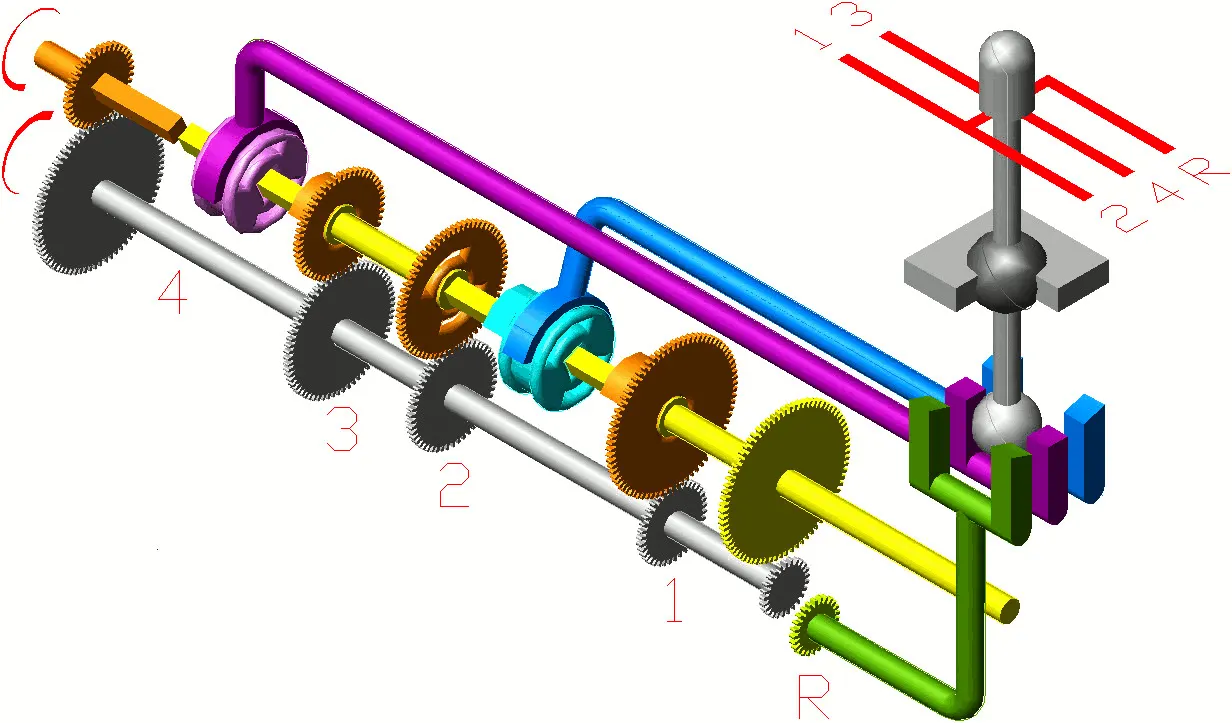
Gears are mechanisms that mesh together via teeth and are used to transmit rotary motion from one shaft to another. Gears are defined by two important items: radius and number of teeth. They are typically mounted, or connected to other parts, via a shaft or base. When the driver manually selects at which gear should the car run, he changes the gears using a clutch. Clutch is the part which connects the engine to transmission. when driver needs a gear change, he presses clutch pedal/lever, which disconnects the wheels and engine. When he changes the gear and releases the clutch, he which puts the wheel back in connection with the engine. With changed gear, the speed range of the car changes. When car speeds up, the engine cannot speed up in the same proportion, so there are gears involved which match the engine speed to the wheel speed so that we can drive faster or slower than the engine speed.
SIMULINK MODEL:
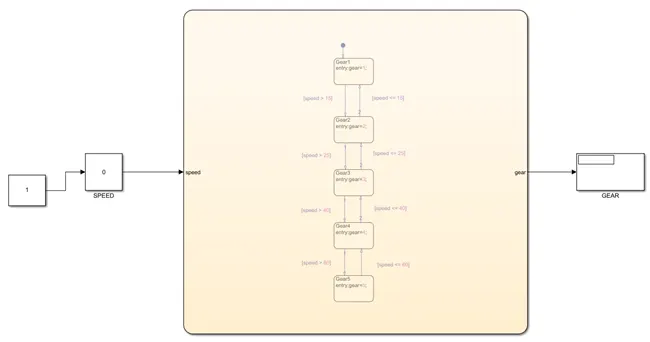
CHART:
MODEL EXPLANATION:
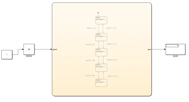
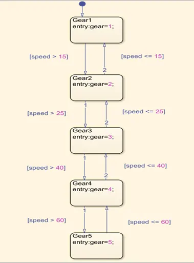
Open a blank model and select the chart block from the browser. Double click on it to begin with the state-flow logic creation. Create five states using the chart option from the palette available on the left side of the window. Enter the state names starting from gear1 to gear 5. Give the entry values as their corresponding gear no’s. We provide a varying input as speed and accordingly the gears are selected. If the speed of the vehicle is greater than the earlier gear’s speed range, the gear is changed.
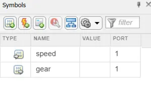
Then all the symbols that are used in the state-flow are named and categorized accordingly in the symbols pane.
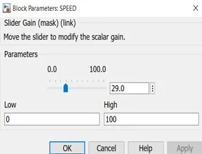
After coming out of the chart, we give a varying speed input using a slider gain block. A display block is connected to the gear port of chart to view the gear number.
RESULT:
The stop time is given as inf and the slider is varied constantly to view the output.