Week -2
1.Simulink model of Doorbell using solenoid
AIM:
Make a Simulink model of Doorbell using solenoid block
CONDITIONS:
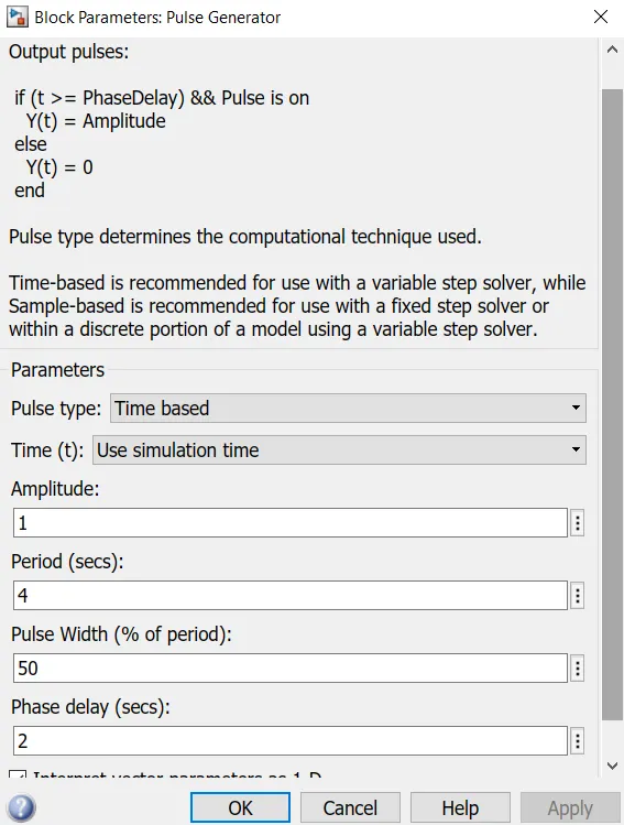
The switch should be closed for 2 sec and then released.
BLOCKS USED IN MODEL:
- Scope
- Battery
- Pulse generator
- Switch
- Solenoid
- Mechanical translational reference
- Solver configuration
- Ideal Translational motion sensor
- PS Simulink converter
- Simulink PS converter
- Electrical reference
THEORY:
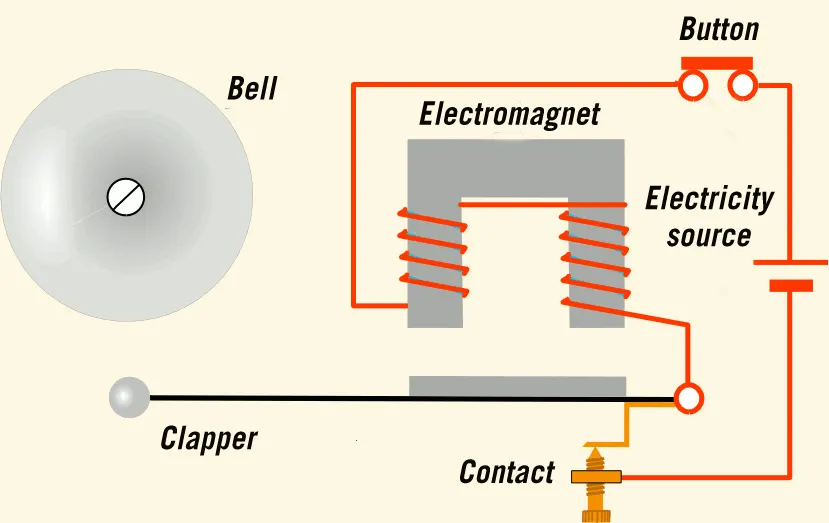
When a doorbell button is pressed, it completes the electric circuit. Thereby current flows through the solenoid. The solenoid is a three-dimensional structure of wire, but when you pass current through it, it becomes an electromagnet. The current passing through the solenoid creates a magnetic field which is used to drive a sound.
SIMULINK MODEL:
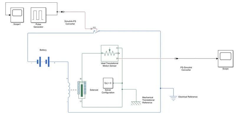
Initially the pulse generator is connected to the PS port in the switch using a Simulink-PS converter. A delay of 2 sec is given to the pulse generator.
A scope is connected with the PS converter to monitor its behavior. A solenoid is introduced and a battery is connected to it.
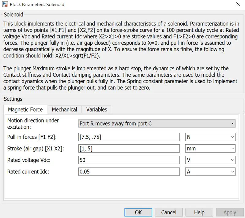
The switch is also connected to the same circuit. The motion of the solenoid plunger is measured using a ideal translational motion sensor. The R ports of the motion sensor and solenoid are connected together. Similarly, the C ports of the solenoid and motion sensor are connected with each other. The mechanical translational reference block and electrical reference is added in the appropriate places. A solver configuration block is added to execute the block without any errors. The P port of the ideal translational motion sensor is connected to the scope using a PS-Simulink converter. The movements of the plunger are being plotted in this scope.
RESULTS:
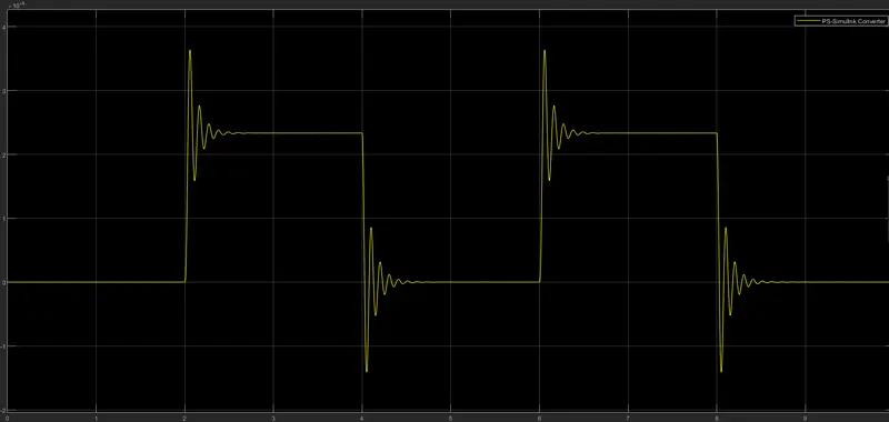
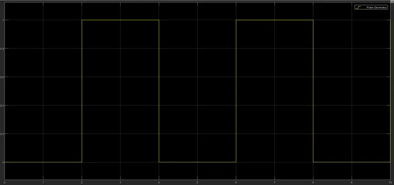
The plunger movement as recorded by the scope is shown above. The simulation was run for 10 sec. It is observed that for every 2 sec interval, the bell is ringing. As the critical damping is 1, the plunger movement quickly comes to rest. The scope results of the pulse generator is given below.
2. THERMISTOR CONTROLLED FAN
AIM:
Make a Simulink model of a thermistor controlled fan.
CONDITIONS:
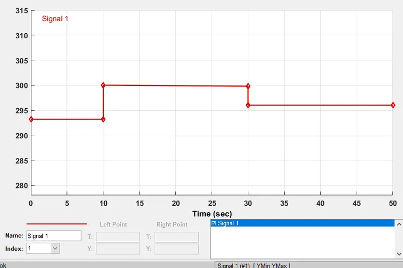
Temperature source: 20 °C from 0 to 10 seconds, 27 °C from 10 to 30 seconds, 23 °C from 30 to 50 seconds. Fan conditions: ON if the temperature above 25 °C, OFF otherwise
BLOCKS USED IN MODEL:
- Signal builder
- Solver configuration
- Thermal reference
- Electrical reference
- Simulink-PS converter
- PS-Simulink converter
- Controlled temperature source
- Thermistor
- Battery
- Voltage sensor
- Resistor
- Switch
- Scope
- Display
- lamp
- constants
THEORY
Thermistor is a type of resistor whose resistance varies with temperature. There are two types of thermistors namely PTC and NTC. In PTC thermistor, resistance increases with increase in temperature. In NTC resistor, resistance decreases with increase in temperature.
SIMULINK MODEL:
We give the input signal using the signal builder block. The input signal is being fed in the signal builder according to the conditions given.
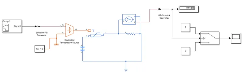
The signal is being fed to the S port of the controlled temperature source using the Simulink-PS converter block. The A port is connected to thermal reference. The B port is connected to the thermal port T of the thermistor. A resistor is connected in series with the thermistor. A voltage sensor is connected in parallel to the resistor. A battery is connected in this circuit followed by a electrical reference. The output from voltage sensor is being fed to display block using a PS-Simulink converter. The display block displays the threshold value being measured by the voltage sensor. This threshold is being fed to a 3 pin switch. Constants 0 and 1 are being fed to the other two pins in the switch. Finally a scope is connected to the switch and the output of switch is connected to the lamp.
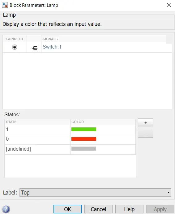
If the resistance across is less than the switch threshold value, then fan goes to off state and the lamp turns to red. If the resistance across is greater than the threshold, then fan goes to on state and the lamp turns green.
WHEN FAN IS ON:
The fan turns on when temp is greater than 25°C. The stop time is 25 seconds
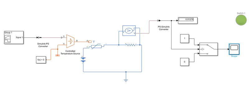
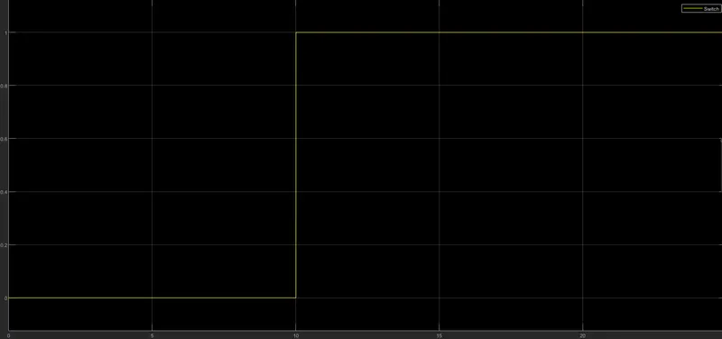
The graph above shows that from 0 - 10 seconds, the temperature is 20°C and the fan is off. The fan gets turned on from 10 - 30 seconds where the temperature is 27°C .
WHEN FAN IS OFF:
The fan turns off when the temp is less than 25°C. The stop time is 50 seconds.
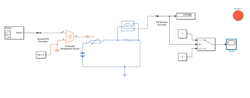
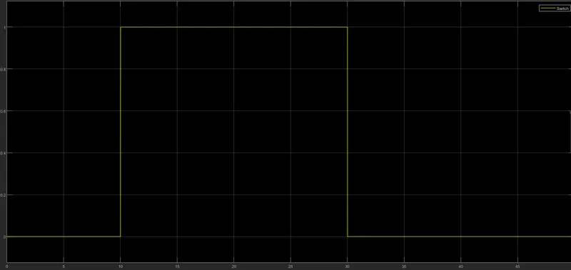
In the above plot at 30 seconds, the fan goes off again as the temperature reaches 23°C.